
Arrangement for Cooling of an Electrical Machine

Inactive Publication Date: 2010-04-29
SIEMENS AG
View PDF3 Cites 3 Cited by
  • Summary
  • Abstract
  • Description
  • Claims
  • Application Information

AI Technical Summary

Benefits of technology

[0029]It is the aim of the present invention, to provide an improved arrangement for cooling of an electrical machine, especially to be used at hot sites.
[0036]So according to the invention a third cooling-system as described above is brought additionally to an existing cooling-system to enhance the cooling capacity of the whole electrical machine.
[0039]The cooling-arrangement according to the invention allows to cool down active parts, which are located inside the electrical machine, to a temperature that is below the ambient temperature.
[0040]This results in a higher capacity of the active parts. Especially if the electrical machine is a generator or motor it is possible to reduce the amount of copper and magnets for a given size of the generator or motor. This leads directly to reduced costs, as copper is an expensive part of the machine.
[0041]As the amount of used copper and magnets is reduced, it is possible to reduce the size of the generator or motor, too.
[0042]Furthermore the high cooling-capacity per volume of the generator or motor leads to a reduced size of the generator or motor.

Problems solved by technology

This is not possible for a large machine, which shows a relatively small surface per power rating and heat generation.
When the machine is installed under harsh conditions, like it is for generators being used in offshore wind-turbines, the electrical machine need to be totally enclosed, so ambient air is not allowed to circulate through the machine.
This cooling method disadvantageously requires large gas-to-air or gas-to-water heat-exchangers.
Furthermore considerable additional power is required to circulate the cooling-medium inside the machine.
This cooling method suffers from a considerable temperature-gradient, which exists between the windings of the stator and the cooling-medium—due to a moderate heat-conductivity of the laminate-plates.
Because of this it is difficulty to maintain a predetermined winding-temperature, which is below a required maximum-value.
To bring in the cooling-medium hollow ceramic-cooling-pipes are used, which are expensive and difficulty to handle.
It is not possible for offshore-locations to use ambient air for the cooling as described in FIG. 3 as ambient air comprises salt-particles.
To circulate the cooling-medium with high speed induces a high power-consumption needed by pumps of fans, so an overall efficiency of the electrical machine is reduced.
Furthermore a high speed circulating cooling-medium may induce unacceptable noise.
There is one problem remaining: if the electrical machine is located at hot sites as deserts it is not possible to cool down the medium to a temperature, which is below the ambient temperature.
Additionally if the cooling-medium needs to be cooled down close to the ambient temperature then the size of required heat-exchangers has to grow dramatically.

Method used


Image

  • Arrangement for Cooling of an Electrical Machine
  • Arrangement for Cooling of an Electrical Machine
  • Arrangement for Cooling of an Electrical Machine

Examples


first embodiment

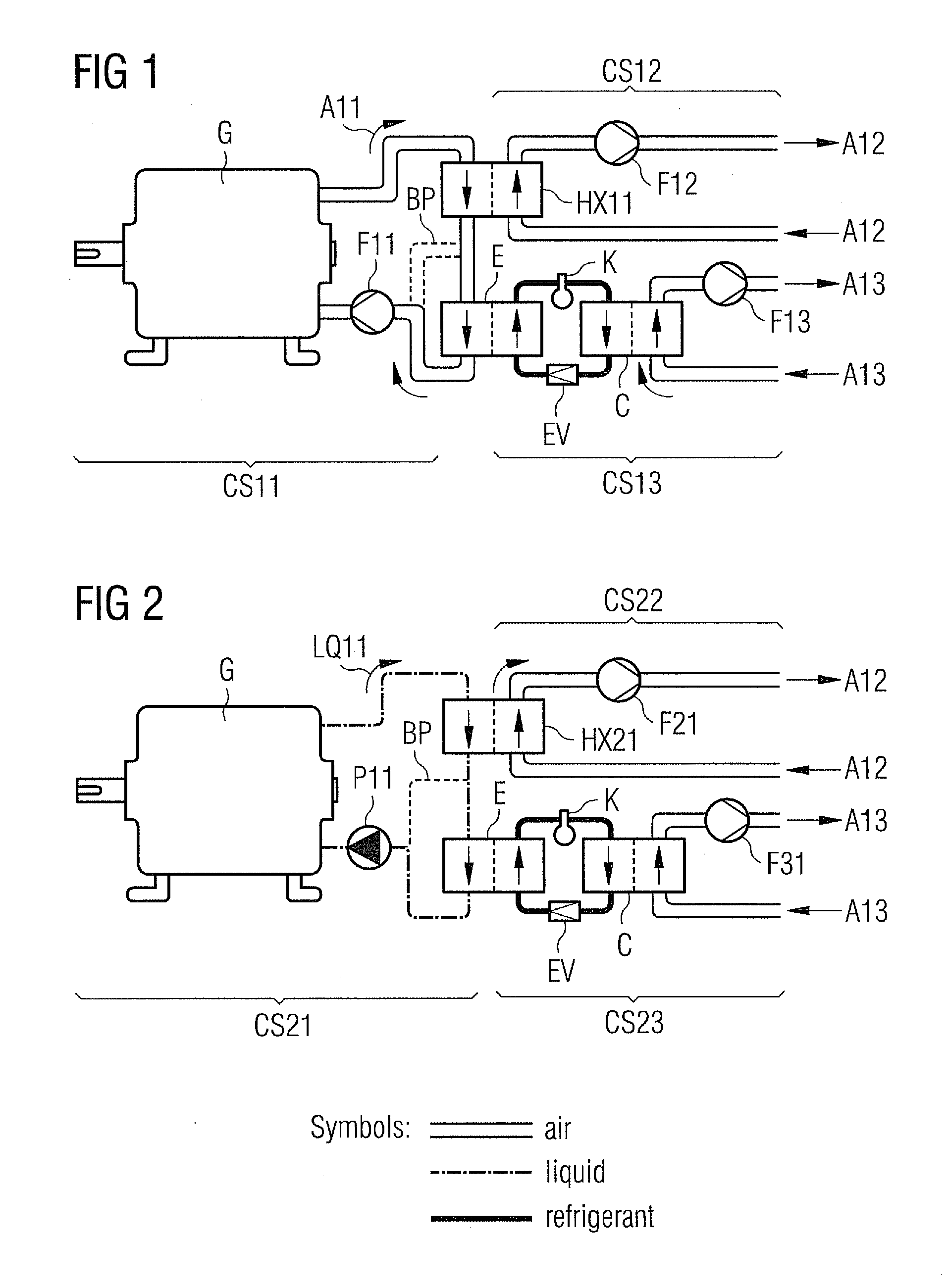
[0048]FIG. 1 shows the inventive cooling-arrangement, which is based on an air-cooled generator G.

[0049]The generator G is located offshore and / or at hot sites in a nacelle of a wind-turbine in a preferred embodiment.

[0050]There is a first cooling system CS11, which is connected with the generator G for its direct cooling. This first cooling-system CS11 comprises a fan F11 to enforce the flow of cooling-air A11 through the generator G.

[0051]There is a second cooling system CS12 with a fan F12. Ambient air A12 is forced to flow through the second cooling-system CS12 by help of a fan F12.

[0052]The second cooling system CS12 is connected with the first cooling-system CS11 via an air-to-air heat-exchanger HX11. The heat-exchanger HX11 is used to hand-over dissipated heat from the cooling-air A11 to the ambient air A12.

[0053]According to the invention there is a third cooling-system CS13, which is a refrigeration-system. The third-cooling-system CS13 is connected with the first cooling-s...

second embodiment

[0058]FIG. 2 shows the inventive cooling-arrangement, which is based on a liquid-cooled generator.

[0059]The generator G is located offshore and / or at hot sites in a nacelle of a wind-turbine in a preferred embodiment.

[0060]There is a first cooling system CS21, which is connected with the generator G for its direct cooling. This first cooling-system CS21 comprises a pump P11 to enforce the flow of a cooling-liquid LQ11 through the generator G.

[0061]There is a second cooling system CS22 with a fan F21. Ambient air A12 is forced to flow through the second cooling-system CS22 by help of the fan F21.

[0062]The second cooling system CS22 is connected with the first cooling-system CS21 via a liquid-to-air heat-exchanger HX21. The heat-exchanger HX21 is used to hand-over dissipated heat from the cooling liquid LQ11 to the ambient air A12.

[0063]According to the invention there is a third cooling-system CS23, which is a refrigeration-system. The third-cooling-system CS23 is connected with the ...


PUM


Abstract

An arrangement for cooling an electrical machine is provided. The electrical machine is connected with a first cooling-system which directly cools the electrical machine. The first cooling-system circulates a first cooling-medium. The first cooling-system is connected with a second cooling-system which delivers heat from the first cooling-system to the second cooling-system. The second cooling-system circulates a second cooling-medium to remove the received heat. The first cooling-system is connected with a third cooling-system, which is a refrigeration-system, to additionally cool down the first cooling-medium of the first cooling-system.

Description

CROSS REFERENCE TO RELATED APPLICATIONS[0001]This application claims priority of European Patent Office application No. 08018799.0 EP filed Oct. 28, 2008, which is incorporated by reference herein in its entirety.FIELD OF INVENTION[0002]The invention relates to a cooling-arrangement of an electrical machine.[0003]In a preferred embodiment the invention relates to a huge electrical machine, which is totally enclosed by a shell or housing.BACKGROUND OF INVENTION[0004]Electrical machines needs cooling to dissipate heat, which is generated during its operation by ohmic resistance, by iron hysteresis, etc.[0005]It is possible to cool a small electrical machine by a heat-transfer from the inside of the machine to its surface.[0006]This is not possible for a large machine, which shows a relatively small surface per power rating and heat generation.[0007]When a machine is installed indoor at a dry atmosphere it is possible to operate the machine without a housing, so a cooling is achieved b...

Claims


Application Information

Patent Timeline
IPC IPC(8): H02K9/19F28D15/00H02K9/10
CPCF25D17/02Y02E10/725H02K9/19Y02E10/72
Inventor GUNDTOFT, SOEREN
Owner SIEMENS AG
Features
  • Generate Ideas
  • Intellectual Property
  • Life Sciences
  • Materials
  • Tech Scout
  • Unparalleled Data Quality
  • Higher Quality Content
  • 60% Fewer Hallucinations
Learn More