Red fluorescent substance and light-emitting device employing the same

a technology of fluorescent substances and light-emitting devices, which is applied in the direction of discharge tubes/lamp details, discharge tubes luminescent screens, discharge tubes/lamp details, etc., can solve the problems of serious “color drift” and loss of light emitted from fluorescent substances, and achieve the effect of further reducing color dri

Inactive Publication Date: 2010-04-29
KK TOSHIBA
View PDF5 Cites 112 Cited by
  • Summary
  • Abstract
  • Description
  • Claims
  • Application Information

AI Technical Summary

Benefits of technology

[0103]The blue fluorescent substance is preferably incorporated in the device of the present invention since the color drift can be further reduced, provided that it undergoes thermal quenching at the same level as the red and green fluorescent substances. However, as for the wavelength range of luminescence, the blue fluorescent substance does not need to be restricted as strictly as the red or green one. That is because the luminescence emitted from the blue fluorescent substance can be compensated by the emission from the light-emitting chip of LED.
[0104]The light-emitting chip used in the light-emitting device is properly selected according to the fluorescent substances used together in the device. It is necessary for the light-emitting chip to emit light capable of exciting the fluorescent substances. Further, in the case where the light-emitting device is wanted to give off white light, the light-emitting chip preferably emit light capable of compensating luminescence from the fluorescent substances.
[0105]In consideration of the above, the light-emitting chip (S1) is so selected that it emits light in the wavelength range of 250 to 500 nm in the case where the red and green fluorescent substances are used in the device. On the other hand, if the red, green and blue fluorescent substances are used, the light-emitting chip (S2) is so selected that it emits light in the wavelength range of 250 to 43...

Problems solved by technology

Consequently, the light emitted from the fluorescent substances is liable to lose the balance with that from the LED.
Further, since the thermal quenching of the green fluorescent substance does not always proceed in the same way as that of the red flu...

Method used


Image

  • Red fluorescent substance and light-emitting device employing the same
  • Red fluorescent substance and light-emitting device employing the same
  • Red fluorescent substance and light-emitting device employing the same

Examples


example 1

[0114]As the starting materials, Sr3N2, EuN, Si3N4, Al2O3 and AlN in the amounts of 2.676 g, 0.398 g, 6.080 g, 0.680 g and 0.683 g, respectively, were weighed and dry-mixed in an agate mortar in a vacuum glove box. The mixture was placed in a BN crucible and then fired at 1850° C. for 4 hours under 7.5 atm of N2 atmosphere, to synthesize a fluorescent substance (G1) whose designed composition was (Sr0.92Eu0.08)3Al3Si13O2N21.

[0115]The fluorescent substance (G1) obtained by firing was in the form of yellowish green powder, and was observed to emit green luminescence when excited by black light.

[0116]Independently, as the starting materials, Sr3N2, EuN, Si3N4, Al2O3 and AlN in the amounts of 2.579 g, 0.232 g, 4.583 g, 0.476 g and 1.339 g, respectively, were weighed and dry-mixed in an agate mortar in a vacuum glove box. The mixture was placed in a BN crucible and then fired at 1850° C. for 4 hours under 7.5 atm of N2 atmosphere, to synthesize a fluorescent substance (R1) whose designed...

example 2

[0120]The procedure of Example 1 was repeated to synthesize the green fluorescent substance (G1). Thereafter, the procedure of Example 1 was further repeated except for changing the amounts of Sr3N2 and EuN into 2.660 g and 0.093 g, respectively, to synthesize a red fluorescent substance (R2) whose designed composition was (Sr0.98Eu0.02)2Al3Si7ON13. The emission spectrum of the obtained red fluorescent substance (R2) under the excitation at 457 nm was shown in FIG. 4, and the result of component analysis (in terms of molar ratio normalized based on the Al content) was summarized in Table 3.

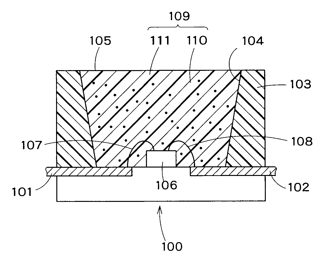
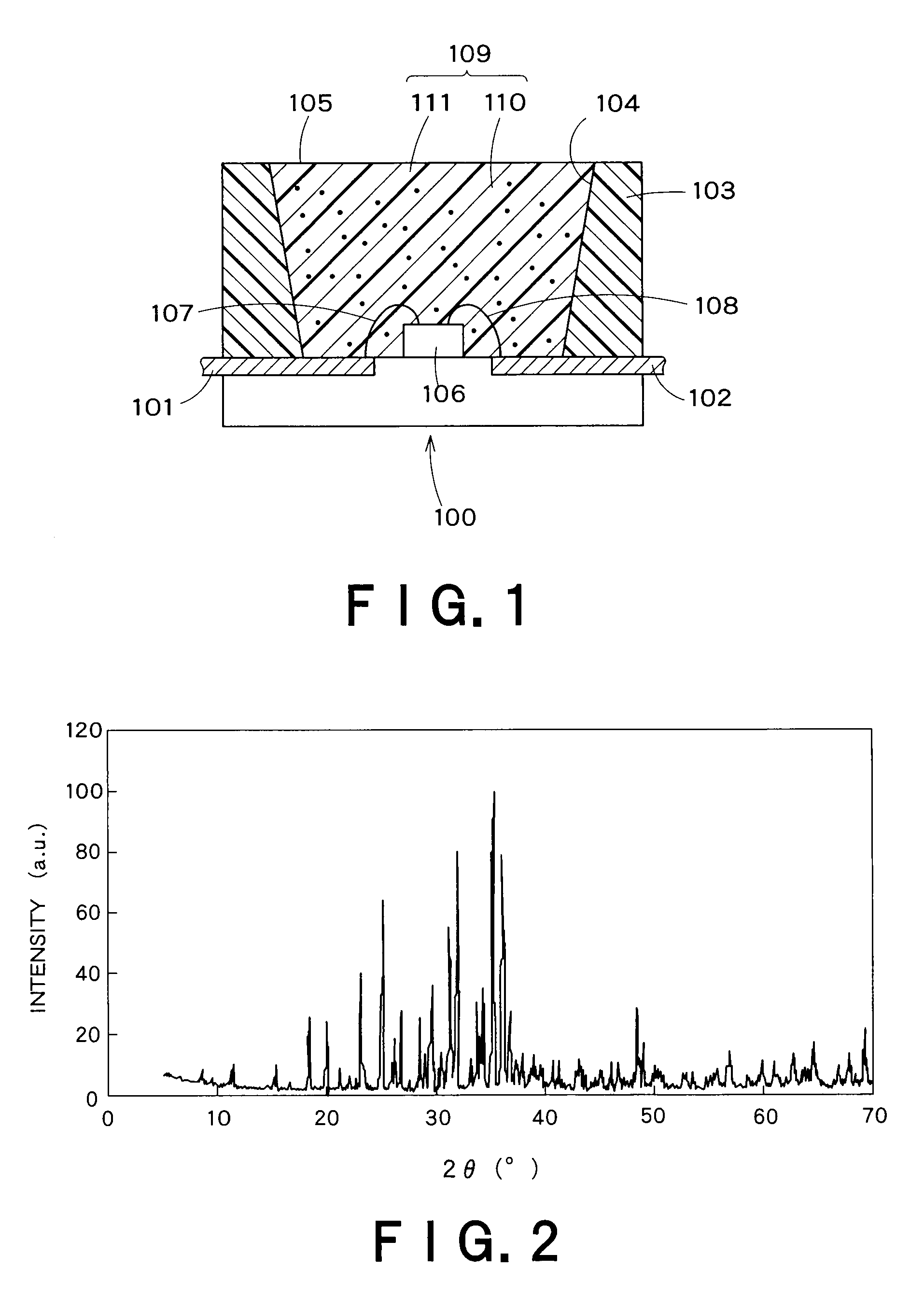
[0121]A light-emitting diode giving an emission peak at 455 nm was soldered on an 8 mm-square AlN package, and was connected to electrodes by way of gold wires. The light-emitting diode was then domed with transparent resin, and the dome was coated with a layer of transparent resin containing 30 wt. % of the red fluorescent substance (R2) giving an emission peak at 577 nm. Further, another layer o...

example 3

[0123]The procedure of Example 1 was repeated to synthesize the green fluorescent substance (G1). Thereafter, the procedure of Example 1 was further repeated except for changing the amounts of Sr3N2 and EuN into 2.443 g and 0.465 g, respectively, to synthesize a red fluorescent substance (R3) whose designed composition was (Sr0.9Eu0.1)2Al3Si7ON13. The emission spectrum of the obtained red fluorescent substance (R3) under the excitation at 457 nm was shown in FIG. 4, and the result of component analysis (in terms of molar ratio normalized based on the Al content) was summarized in Table 3.

[0124]A light-emitting diode giving an emission peak at 455 nm was soldered on an 8 mm-square AlN package, and was connected to electrodes by way of gold wires. The light-emitting diode was then domed with transparent resin, and the dome was coated with a layer of transparent resin containing 30 wt. % of the red fluorescent substance (R3) giving an emission peak at 607 nm. Further, another layer of ...


PUM


Abstract

The present invention provides a red fluorescent substance and a light-emitting device utilizing the substance. This device less suffers from color drift even when working with high power. The light-emitting device comprises a blue LED, a green fluorescent substance of Sr3Al3Si13O2N21 activated with a luminescent center, and the red fluorescent substance. The red fluorescent substance contains an inorganic compound comprising a metal element M, a trivalent element M1 other than the M, a tetravalent element M2 other than the M, and nitrogen element. In the inorganic compound, the M is partly replaced with a luminescent center element EC. The red fluorescent substance has basically the same crystal structure as Sr2Al3Si7ON13. The red fluorescent substance emits luminescence having a peak in the range of 580 to 650 nm when excited with light of 250 to 500 nm.

Description

CROSS-REFERENCE TO RELATED APPLICATIONS[0001]This application is based upon and claims the benefit of priority from the prior Japanese Patent Application No. 2008-278642, filed on Oct. 29, 2008; the entire contents of which are incorporated herein by reference.BACKGROUND OF THE INVENTION[0002]1. Field of the Invention[0003]The present invention relates to a light-emitting device utilizing fluorescent substances. In particular, this invention relates to a light-emitting device in which plural fluorescent substances giving emissions at different wavelengths are used in combination.[0004]2. Background Art[0005]LED lamps, which utilize light-emitting diodes, are used in many displaying elements of instruments such as mobile devices, PC peripheral equipments, OA equipments, various kinds of switches, light sources for backlighting, and indicating boards. The LED lamps are strongly required not only to have high efficiency, but also to be excellent in color rendition when used for general...

Claims


Application Information

Patent Timeline
IPC IPC(8): H01J1/63C09K11/64C09K11/59
CPCC09K11/0883C09K11/7734H01L2224/45144H01L2224/48091H01L2924/00014H01L2924/00C09K11/77348
Inventor FUKUDA, YUMIMATSUDA, NAOTOSHI
Owner KK TOSHIBA
Why Eureka
Try Eureka