
Surface plasmon antenna with propagation edge and near-field light generating element

a plasmon antenna and propagation edge technology, applied in special recording techniques, instruments, nuclear engineering, etc., can solve problems such as difficult problems, head cannot write data to magnetic recording medium, and degradation of magnetization thermal stability

Active Publication Date: 2010-04-29
TDK CORPARATION
View PDF18 Cites 117 Cited by
  • Summary
  • Abstract
  • Description
  • Claims
  • Application Information

AI Technical Summary

Benefits of technology

[0015]Therefore, an object of the present invention is to provide a surface plasmon antenna that can be set so that the emitting position on the end surface of the surface plasmon antenna where near-field light is emitted is located sufficiently close to the end of a magnetic pole, and is to provide a near-field light generating element provided with the surface plasmon antenna.
[0020]In the above-described plasmon antenna, the edge for propagating surface plasmon is a very narrow propagation region. Therefore, the near-field light generating end surface, which appears as a polished surface processed through polishing in the manufacturing of the plasmon antenna, can be made a shape with a very small size, and further can be set so that surface plasmon propagates to reach the near-field light generating end surface reliably. Further, by adjusting the shape and size of the near-field light generating end surface, the emitting position of near-field light on the end surface can be controlled.
[0028]In the above-described thermal-assisted magnetic recording head, by adjusting the shape and size of the near-field light generating end surface, the emitting position of near-field light on the end surface can be set to be closer to the magnetic pole. As a result, write field with sufficiently large gradient can be applied to a sufficiently heated portion of the magnetic recording layer of the magnetic recording medium. This enables a stable thermal-assisted write operation to be reliably achieved.
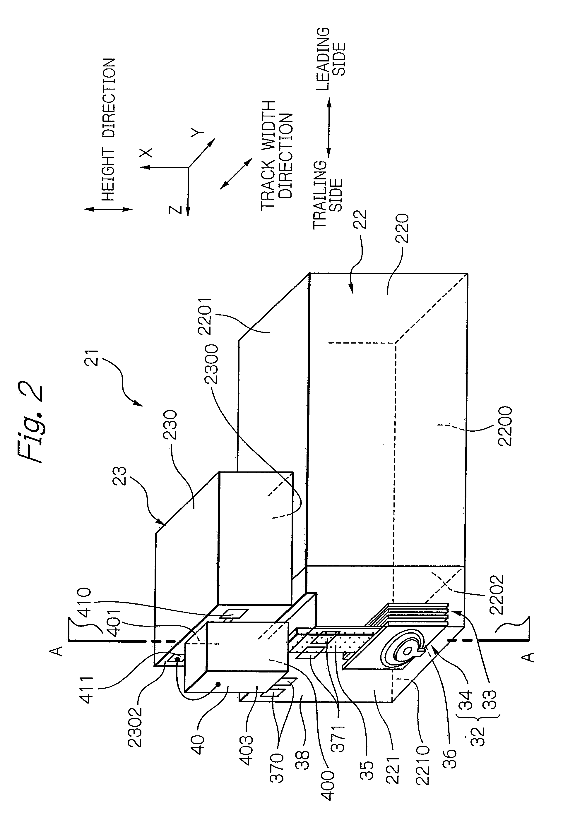
[0031]Further, in the thermal-assisted magnetic recording head according to the present invention, the near-field light generating end surface of the plasmon antenna preferably has a triangular shape in which one apex is an end of the edge. In the case, the near-field light generating end surface preferably has a triangular shape with a height of 30 nm (nanometers) or less, and more preferably with a height of 20 nm or less. And the distance between the near-field light generating end surface of the plasmon antenna and an end surface of the magnetic pole on the opposed-to-medium surface is at least 20 nm, and more preferably at least 30 nm. These conditions enable the emitting position of near-field light on the near-field light end surface to be set to be closer to the end surface of the magnetic pole. As a result, write field with sufficiently large gradient can be more reliably applied to a sufficiently heated portion of the magnetic recording medium. Here, it is also preferable that the near-field light generating end surface of the plasmon antenna has a shape of a rhombus in which one apex is an end of the edge.

Problems solved by technology

However, the decrease in size of the magnetic microparticles raises a problem of degradation in thermal stability of the magnetization due to the decrease in volume.
Therefore, the head cannot write data to the magnetic recording medium when the anisotropic magnetic field (coercive force) of the medium exceeds the write field limit.
However, when such a plasmon antenna is used as a near-field light generating part to implement thermal-assisted magnetic recording, a difficult problem can arise as described below.
If this is the case, it will be difficult to properly read the servo signal during writing in which the plasmon antenna is used to irradiate the magnetic recording medium with near-field light.
This means that the light use efficiency of the plasmon antenna described above can be further degraded because of increased thermal disturbance of free electrons in the plasmon antenna.
Therefore, this approach is difficult to implement.
However, in this case, the distance by which surface plasmon propagates increases and so does the amount of energy absorbed into the surface plasmon antenna, increasing propagation loss.

Method used


Image

  • Surface plasmon antenna with propagation edge and near-field light generating element
  • Surface plasmon antenna with propagation edge and near-field light generating element
  • Surface plasmon antenna with propagation edge and near-field light generating element

Examples


Embodiment Construction

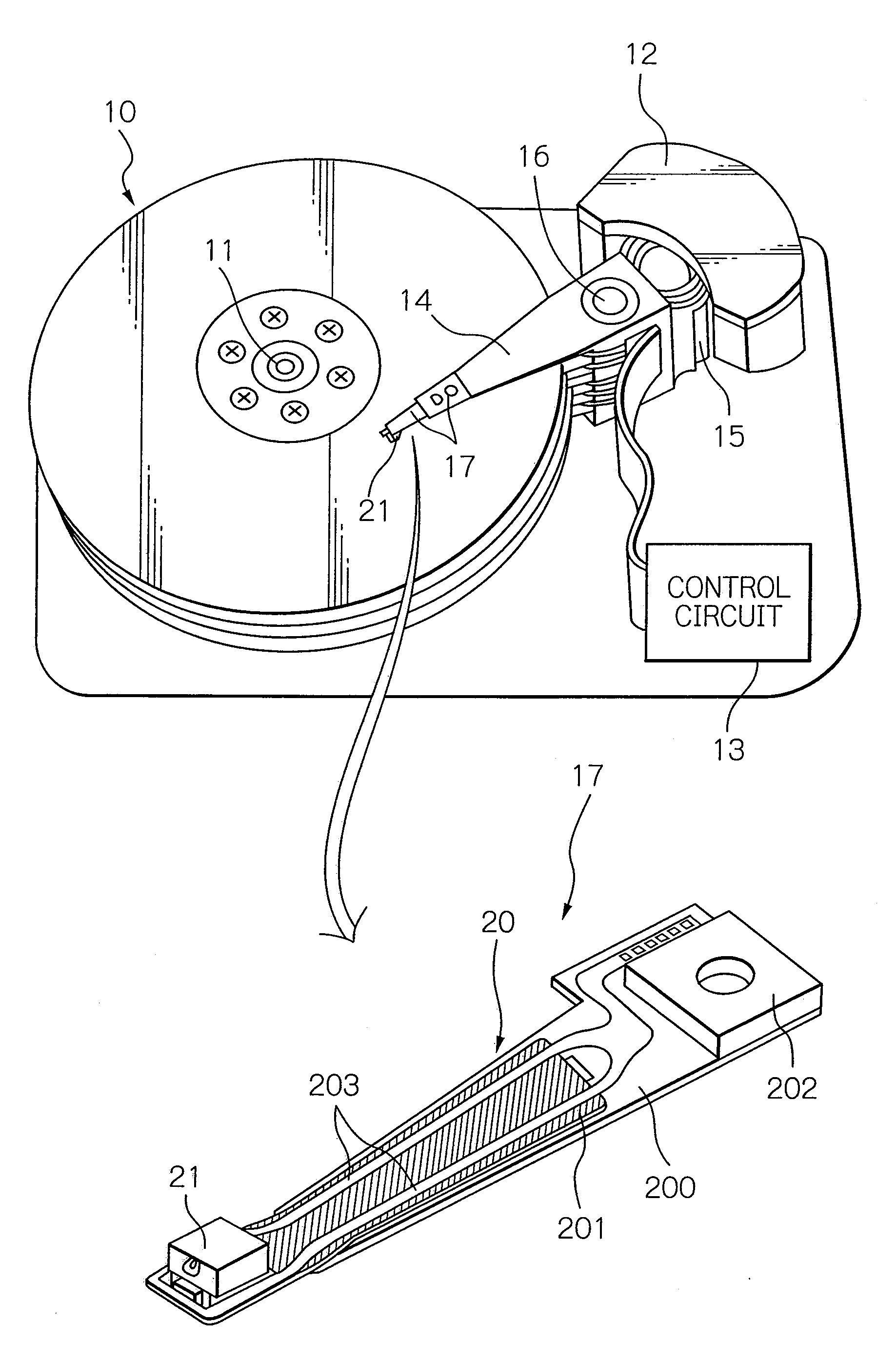
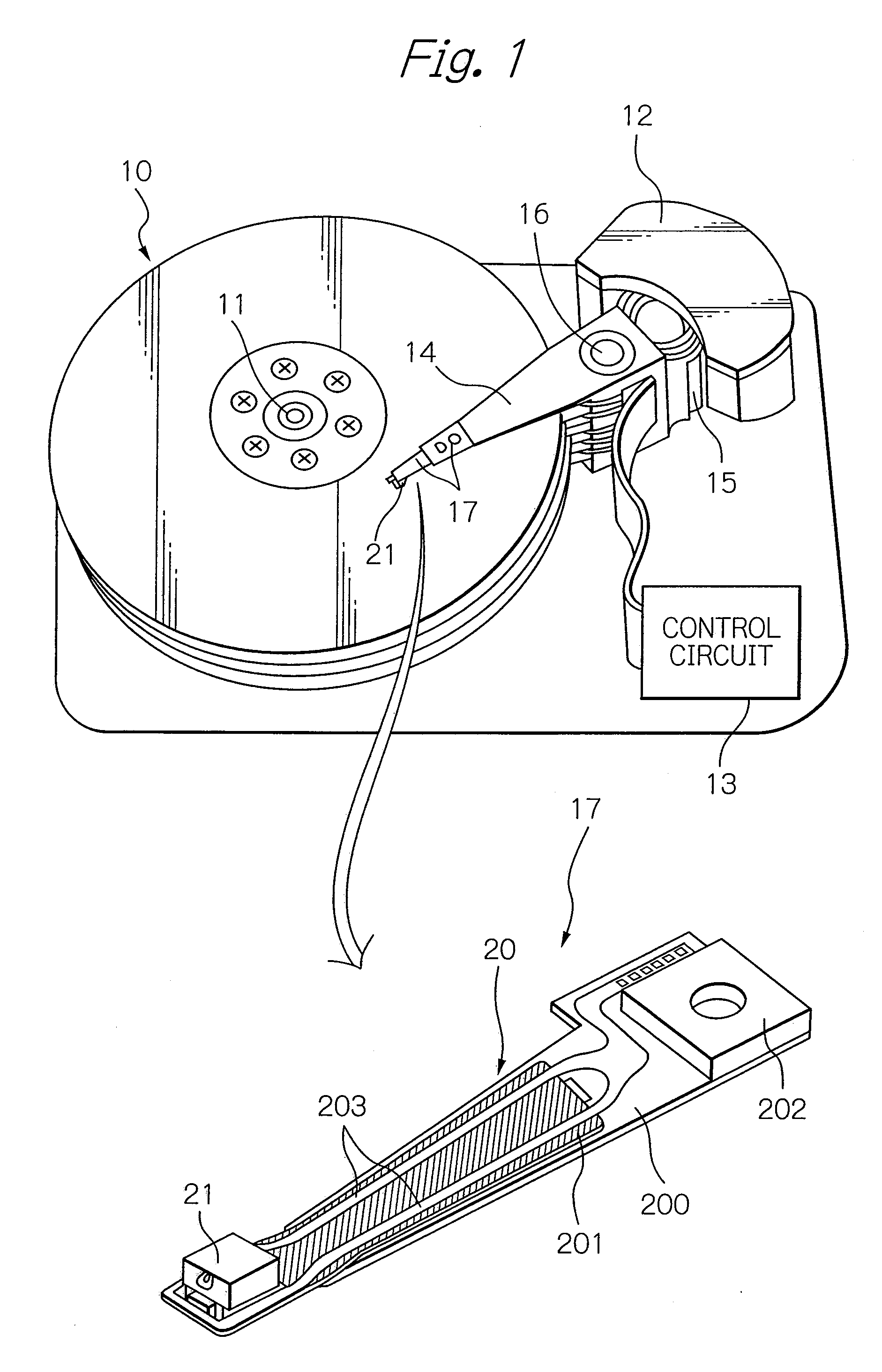
[0056]FIG. 1 shows a perspective view schematically illustrating a structure of a major part in one embodiment of a magnetic recording apparatus and an HGA according to the present invention. Here, in the perspective view of the HGA, the side of the HGA, opposed to the surface of the magnetic recording medium, is presented as the upper side.

[0057]A magnetic disk apparatus as a magnetic recording apparatus shown in FIG. 1 includes: a plurality of magnetic disks 10 as magnetic recording media, rotating around a rotational axis of a spindle motor 11; an assembly carriage device 12 provided with a plurality of drive arms 14 thereon; a head gimbal assembly (HGA) 17 attached on the top end portion of each drive arm 14 and provided with a thermal-assisted magnetic recording head 21 as a thin-film magnetic head; and a recording / reproducing and light-emission control circuit 13 for controlling write / read operations of the thermal-assisted magnetic recording head 21 and further for controllin...


PUM


Abstract

Provided is a surface plasmon antenna that can be set so that the emitting position on the end surface of the plasmon antenna where near-field light is emitted is located sufficiently close to the end of a magnetic pole. The surface plasmon antenna comprises an edge having a portion for coupling with a light in a surface plasmon mode. The edge is provided for propagating surface plasmon excited by the light and extends from the portion to a near-field light generating end surface that emits near-field light. The edge for propagating surface plasmon is a very narrow propagation region. Therefore, the near-field light generating end surface, which appears as a polished surface processed through polishing in the manufacturing of the plasmon antenna, can be made a shape with a very small size, and further can be set so that surface plasmon propagates to reach the end surface reliably.

Description

BACKGROUND OF THE INVENTION[0001]1. Field of the Invention[0002]The present invention relates to a plasmon antenna for generating near-field light by being irradiated with light.[0003]And the present invention relates to a head used for thermal-assisted magnetic recording in which a magnetic recording medium is irradiated with near-field light, thereby anisotropic magnetic field of the medium is lowered, thus data can be written. Further, the present invention relates to a magnetic recording apparatus provided with the head.[0004]2. Description of the Related Art[0005]As the recording density of a magnetic disk apparatus becomes higher, further improvement has been required in the performance of a thin-film magnetic head and a magnetic recording medium. As the thin-film magnetic head, a composite-type thin-film magnetic head is widely used, which has a stacked structure of a magnetoresistive (MR) element for reading data and an electromagnetic transducer for writing data.[0006]Where...

Claims


Application Information

Patent Timeline
IPC IPC(8): G11B5/02G21G4/00
CPCB82Y20/00G02B6/1226G11B2005/0021G11B5/4866G11B2005/001G11B5/314
Inventor SHIMAZAWA, KOJIKOMURA, EIJIITO, YASUHIROTAKAYAMA, SEIICHITOMIKAWA, SATOSHIMIYAUCHI, DAISUKETANAKA, KOSUKE
Owner TDK CORPARATION
Learn More