Solid state lighting apparatus utilizing axial thermal dissipation

Inactive Publication Date: 2010-04-29
THRAILKILL JOHN E
View PDF9 Cites 34 Cited by
  • Summary
  • Abstract
  • Description
  • Claims
  • Application Information

AI Technical Summary

Benefits of technology

[0011]In accordance with the present invention, an apparatus is provided for enhanced thermal dissipation of waste heat generated by a closely spaced array of LED dies. In

Problems solved by technology

In operation, however, these devices are hindered by relatively short operating lifetimes, erratic performance, catastrophic failure that can interfere with automatic or man-life dependent operations and the production of high levels of radiated and convected waste heat which can negatively affect the objects of illumination.
A major shortcoming of the current state of the art of LED technology, however, is its inability to produce adequate lev

Method used


Image

  • Solid state lighting apparatus utilizing axial thermal dissipation
  • Solid state lighting apparatus utilizing axial thermal dissipation
  • Solid state lighting apparatus utilizing axial thermal dissipation

Examples


Embodiment Construction

[0034]The present invention is generally directed to high intensity solid state lighting devices. In particular, the invention relates to the use of a primarily axial thermal dissipation system in order to provide for a lighting apparatus with a predominately axial device form factor, or alternatively, a low profile device form factor.

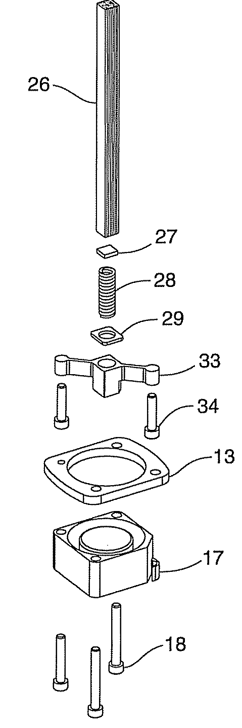
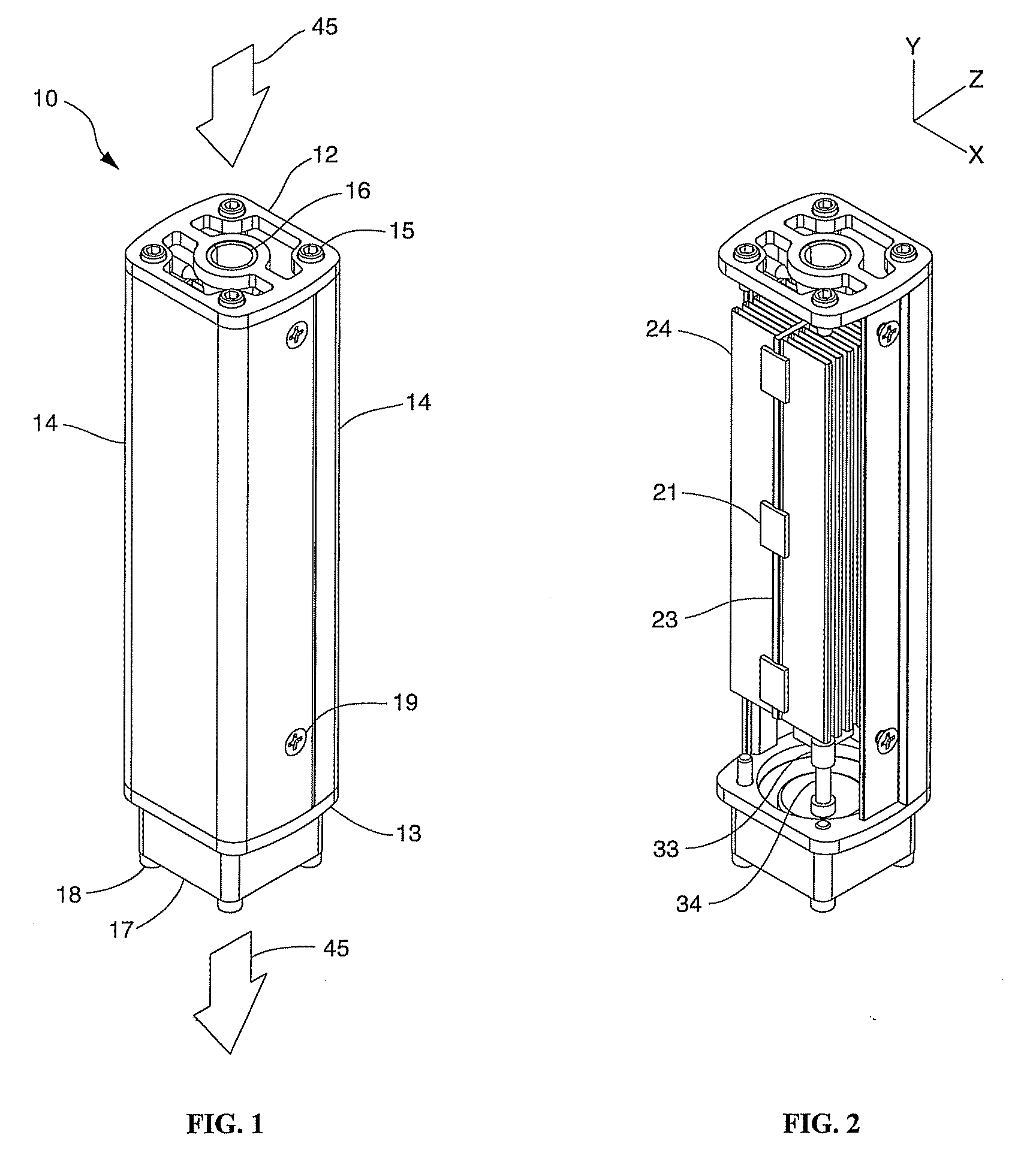
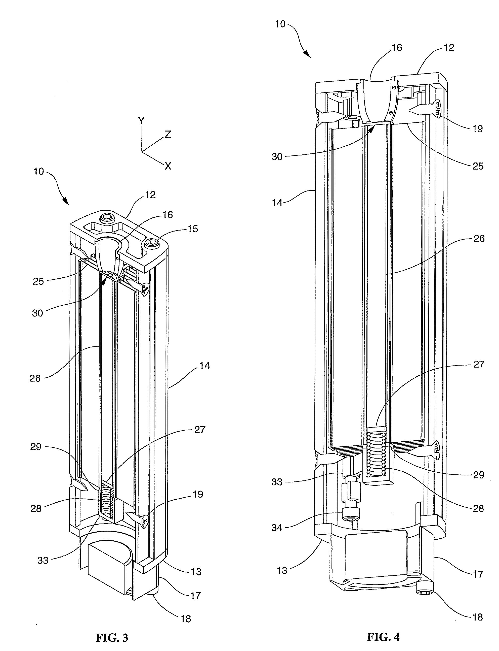
[0035]With reference now to the attached drawings, FIGS. 1-4&FIG. 7 illustrate a high intensity solid state lighting apparatus 10 in accordance with one embodiment of the invention. The lighting apparatus is generally comprised of two functional component groups, the internal component group 50 (shown in FIG. 8) and the external component group 60 (shown in FIG. 9).

[0036]These component groups contribute to the functioning of the lighting apparatus in the following ways: the internal component group 50 serves to generate light and to dissipate the resulting waste heat into an internal structure; the external component group 60 serves to transfer the wa...


PUM


Abstract

A solid state lighting apparatus characterized by its compact, predominately axial form factor, utilizes an axial thermal transfer member constructed of Highly Oriented Pyrolytic Graphite (HOPG) to aid in the dissipation of waste heat generated during its operation. The lighting apparatus is chiefly comprised of a Light Emitting Diode (LED) die array and circuit structure assembly affixed to one end of the axial thermal transfer member and further includes a transversely mounted heat sink structure, running the length of, and being affixed to, opposite sides of the axial member. The axial member serves to distribute waste heat down its length, and simultaneously, into a transverse plane where the waste heat is dissipated into the transversely mounted heat sink structure. A fan may be utilized to evacuate the waste heat out of the lighting apparatus and into the ambient environment.

Description

BACKGROUND OF THE INVENTION[0001]1. Field of the Invention[0002]The present invention relates generally to high intensity, solid state lighting devices. More particularly, the invention relates to the use of a primarily axial thermal dissipation system to provide for a compact, high intensity, solid state lighting device with a predominantly axial overall form factor.[0003]The present invention further relates to the use of a primarily axial thermal dissipation system to provide for a compact, high intensity, solid state lighting device with a comparatively low profile overall form factor.[0004]2. Background Information[0005]High intensity light sources are widely used in projection systems, television backlights, automotive headlamps and other devices that require a relatively compact, high output light source. Some applications require a high intensity light source with limited Etendue (the product of light source area and solid-angle of light output). For these applications, the ...

Claims


Application Information

Patent Timeline
IPC IPC(8): F21V29/00
CPCF21S48/328F21V15/015F21V29/004F21V29/02F21V29/763Y10S362/80F21V29/713F21V29/717F21Y2101/02F21V29/85F21Y2115/10F21V29/67
Inventor THRAILKILL, JOHN E.
Owner THRAILKILL JOHN E
Why Eureka
Try Eureka