Diagnostic and response systems and methods for fluid power systems

a technology of fluid power system and diagnostic system, applied in the direction of testing/monitoring control system, program control, instruments, etc., can solve the problems of inability to reliably detect the exit of imminent failure detection, low reliability, oil spillage, etc., to achieve the effect of generating new revenue streams, improving warranty coverage, and invalidating warranty coverag

Inactive Publication Date: 2010-04-29
THE GATES CORP
View PDF11 Cites 11 Cited by
  • Summary
  • Abstract
  • Description
  • Claims
  • Application Information

AI Technical Summary

Benefits of technology

[0012]Advantageously, the present diagnostic and communication systems and methods enable a hose and fitting manufacturer or supplier to: redefine their approach to distribution networks and to generate new revenue streams; better understand the operational usage of their products; obtain usage data that can be interpreted to provide improved warranty coverage; identify whether a product has been used outside of its designed parameters, thereby invalidating warranty coverage; provide data and market knowledge that will lead to new and improved products; improve its knowledge of hose testing and field use; correlate laboratory tests to service life; provide data to improve equipment performance; and / or better define product specifications based on actual measured performance.
[0013]As further advantages, the present systems and methods may enable an equipment manufacturer or supplier to: employ service indicators for fluid power systems and enable the offering a better indication of service life to end customers; to monitor systems and products after they have been shipped to end users, enabling, among other things, identification of equipment use outside design parameters that would nullify warranty; offer improved equipment performance and warranty coverage; and offer fast response service replacements for field applications; and improve designs and service life.
[0014]Preferably, the present invention will enable equipment end users to: schedule appropriate service and preventative maintenance activities in a timely manner; avoid costly breakdowns on site; monitor performance of their fleets, machines and operators; better assess critical spares inventories; and improve the utilization of machines.

Problems solved by technology

In contrast, hydraulic, or fluid power, equipment components, and particularly fluid power hoses, are service replaceable components which give little or no warning of imminent failure and for which no reliable means of imminent failure detection exits.
Fluid power system failures, particularly hose failures, can lead to expensive downtime, oil spillage, and lost revenue and project delays.
Hence, SAE J1927 or other methodologies fail to provide a means for diagnosing and responding to fluid power system incremental damage and failures in real-time.
Thus, a key difference between the present systems and methods and diagnostic regimes employed in other industries is that the present systems and methods communicate potential fluid power system faults and, where appropriate, vehicle / equipment location.

Method used


Image

  • Diagnostic and response systems and methods for fluid power systems
  • Diagnostic and response systems and methods for fluid power systems
  • Diagnostic and response systems and methods for fluid power systems

Examples


embodiment 200

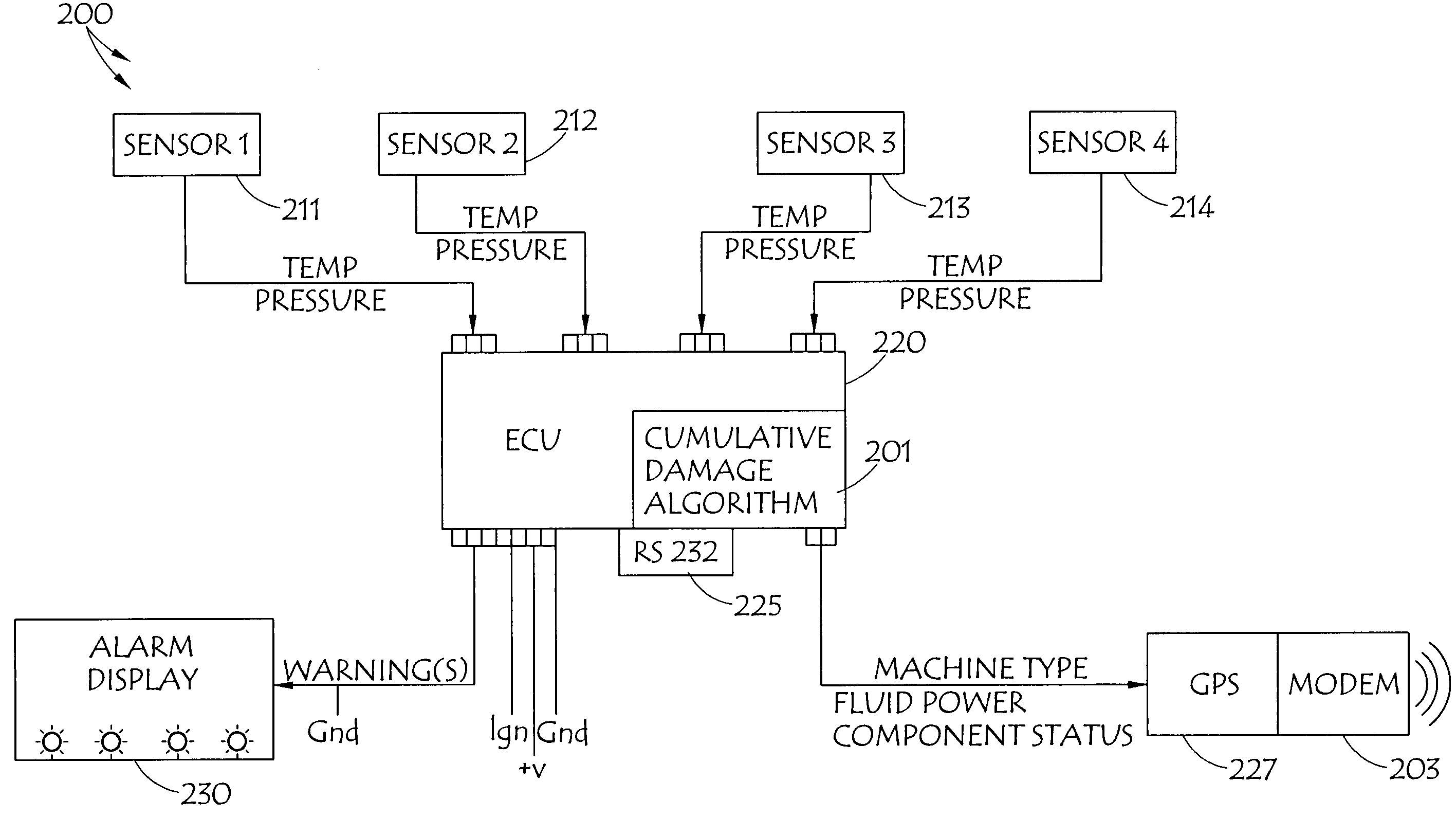
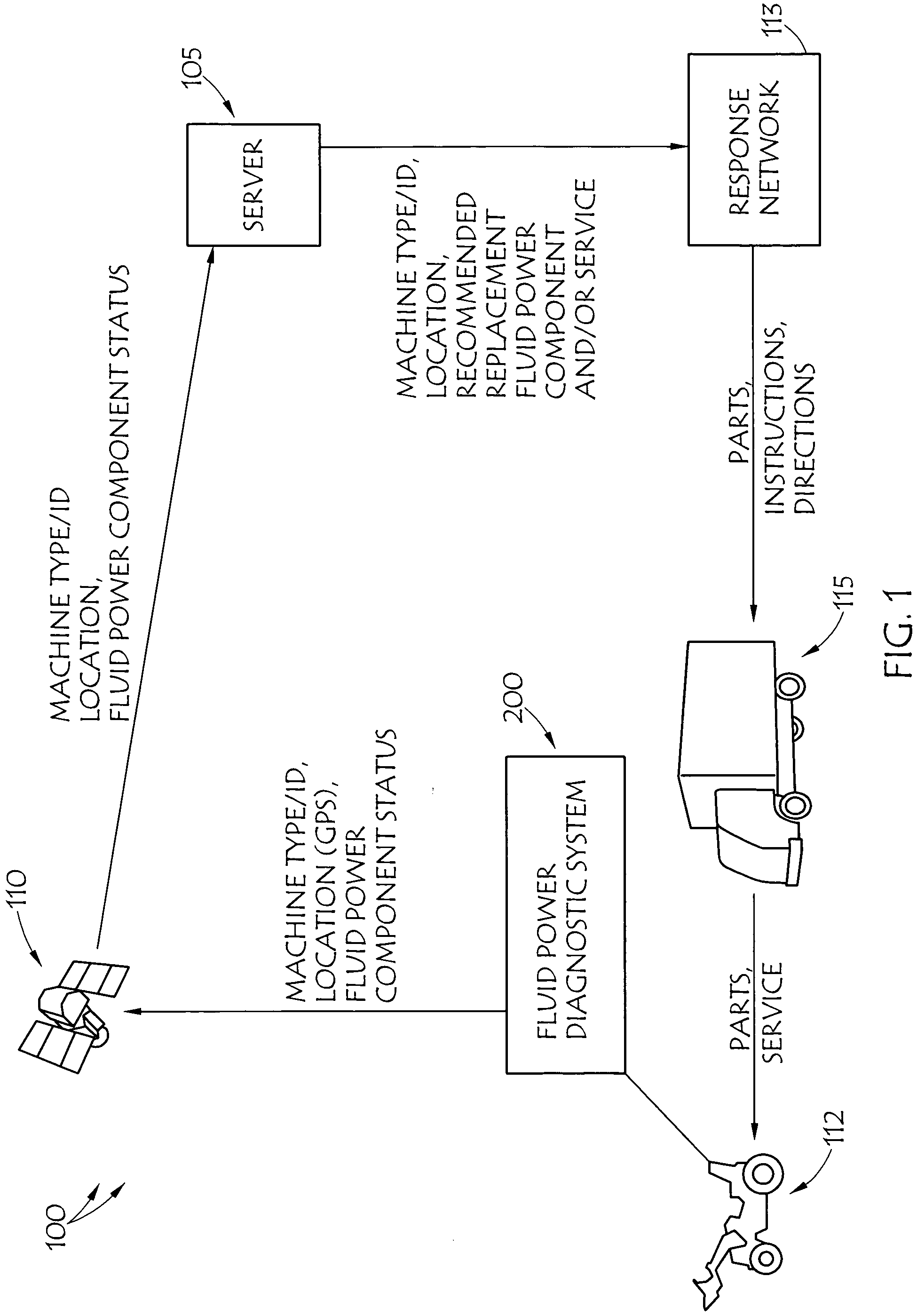
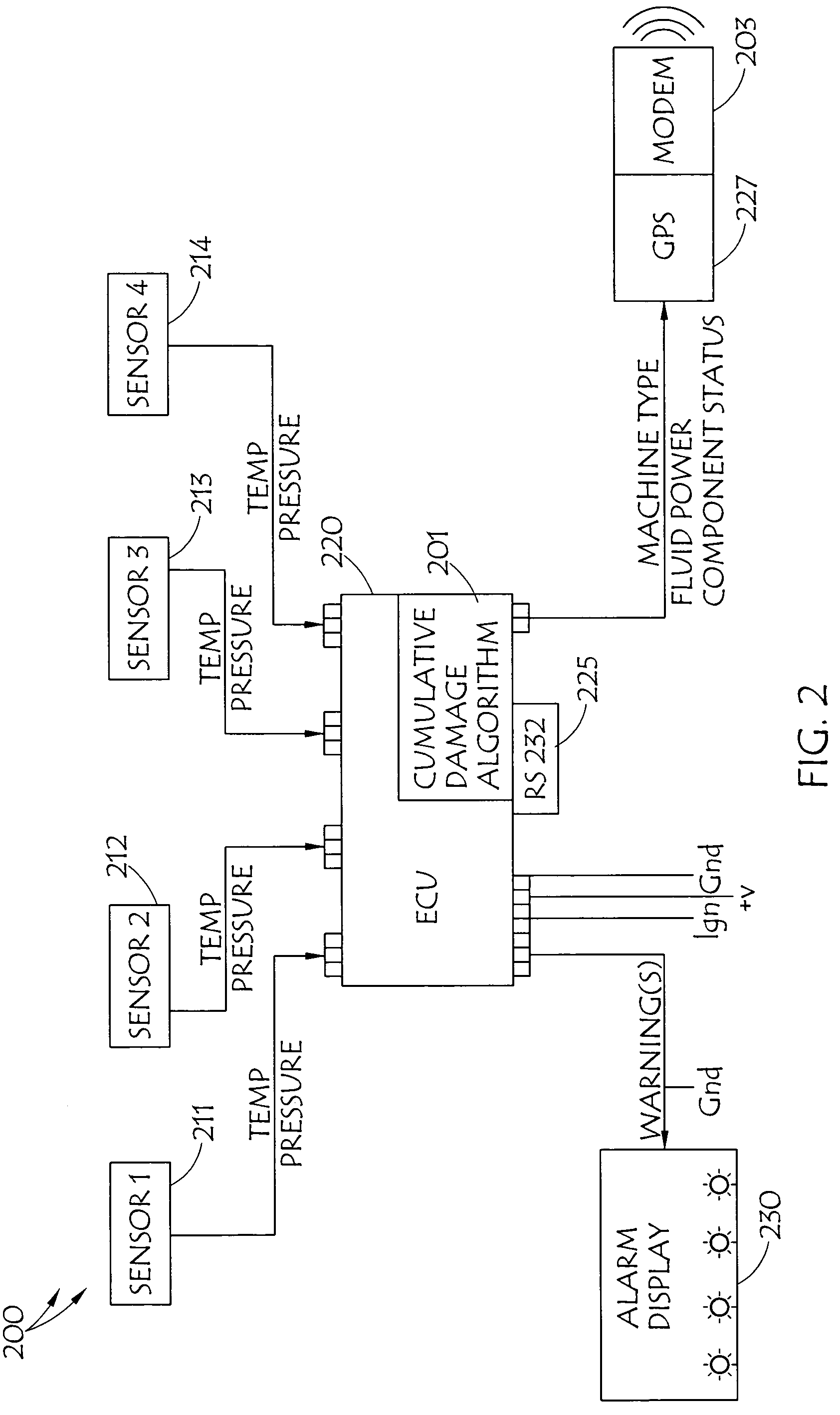
[0030]In FIG. 1, an embodiment of a fluid power diagnostic and response system 100 is illustrated. System 100 preferably employs a fluid power diagnostic system, such as fluid power diagnostic system embodiment 200 illustrated in FIG. 2. Preferably, systems 100 and 200 employ predictive algorithm 201 to indicate when a fluid power system component, such as one or more hoses is nearing the end of its useful life. Various embodiments of systems 100 and 200, such as those illustrated in FIGS. 1 and 2 employ modem 203 to transmit information about the status of the hose, together with various vehicle / equipment specifications, such as the type of machine, a machine identifier and / or various machine fluid power system details, and / or the machine's ground position to central location such as illustrated server 105, through a medium, such as through wireless communication medium 110, such as the illustrated satellite link. However, any wireless link, such as a conventional wireless phone an...

embodiment 400

[0039]FIG. 4 is a flow diagram that includes an embodiment of fluid power hose damage algorithm 201 that may be employed with illustrated embodiment 400 of the present methods. User programmed inputs 401 employed by the present systems and methods may include: maximum rated pressure (Pm) 403 for each hose; threshold pressure 405 that would indicate a pressure peak for a particular hose, usually derived from a percent of the rated pressure for a hose; maximum rated temperature (Tm) 407 for each hose; temperature response curve 409 for each hose; additional variables 411, such as application specific data such as the amount of flex a particular hose is subject to during operation of the subject fluid power system; warning trigger (WT) 413, which may be based on a percent of the useful life of a hose, which has been used; and installed time limit (TL) 415, a time-based limit on the useful life of a hose, such as may be based solely on the age of the hose. User programmed inputs 401 may...


PUM


Abstract

Diagnostic and response systems and methods for a fluid power system acquire data from pressure and temperature sensors disposed in the fluid power system, analyze the data in a failure algorithm to build a history of cumulative damage to hoses in the fluid power system, communicates an indication of potential imminent hose failure to a central location when a level of the cumulative damage indicates imminent failure of a hose, analyze the information at the central location to determine an appropriate response, and transmit information about the fluid power system, including location, and identification of the hose about to fail to a response unit. The response unit responds to the location and replaces the component prior to failure, or the communication might include information that the hose has failed, such that the response unit replaces the failed hose to return the fluid power system to normal operation.

Description

CROSS-REFERENCE TO RELATED APPLICATION[0001]This application is related to concurrently filed U.S. patent application Serial Number [Attorney Docket No. H07-149A1], of the same title, which is incorporated herein by reference.BACKGROUND OF THE INVENTION[0002]1. Field of the Invention[0003]This invention relates generally to fluid power systems and components, more particularly to the monitoring and maintenance of such systems, and specifically to diagnostic and response systems and methods for fluid power systems and components, such as hoses.[0004]2. Description of the Prior Art[0005]The principal of modern diagnostic systems is to use sensing technology and software to read and interpret real world events and communicate the data to alert users to situations that may require some form of intervention. Diagnostic systems are fundamental to equipment performance and longevity in the automotive, fleet transportation and aerospace industries. Diagnostic systems which communicate fault...

Claims


Application Information

Patent Timeline
Patent Type & Authority Applications(United States)
IPC IPC(8): G06F11/30
CPCG05B2219/24053G05B2219/24065G05B23/0283G05B2219/24077G05B2219/24075
Inventor KEAST, GEOFFREY RICHARDELLIS, MICHAEL H.SWIFT, JONATHAN CLARKRAILSBACK, LAYNEGILBREATH, DONALD R.
Owner THE GATES CORP
Why Eureka
Try Eureka