Method and Device for Demodulation of Signals

a signal and demodulation technology, applied in the field of signal demodulation, can solve the problems of low frequency noise in the rectified output, difficult to detect, and high cost, and achieve the effect of improving the demodulation of the output signal

Active Publication Date: 2010-05-06
ABB (SCHWEIZ) AG
View PDF3 Cites 5 Cited by
  • Summary
  • Abstract
  • Description
  • Claims
  • Application Information

AI Technical Summary

Benefits of technology

[0019]The object of the present invention is to provide an improved demodulation ...

Problems solved by technology

This can be particularly difficult with magnetoelastic load cells, since their impedance is nonlinear and changes with the mechanical load on the transducer.
This puts high demand on the electronics of the excitation unit, and thus makes it expensive.
A third difficulty in using phase sensitive detection is ...

Method used


Image

  • Method and Device for Demodulation of Signals
  • Method and Device for Demodulation of Signals
  • Method and Device for Demodulation of Signals

Examples


Embodiment Construction

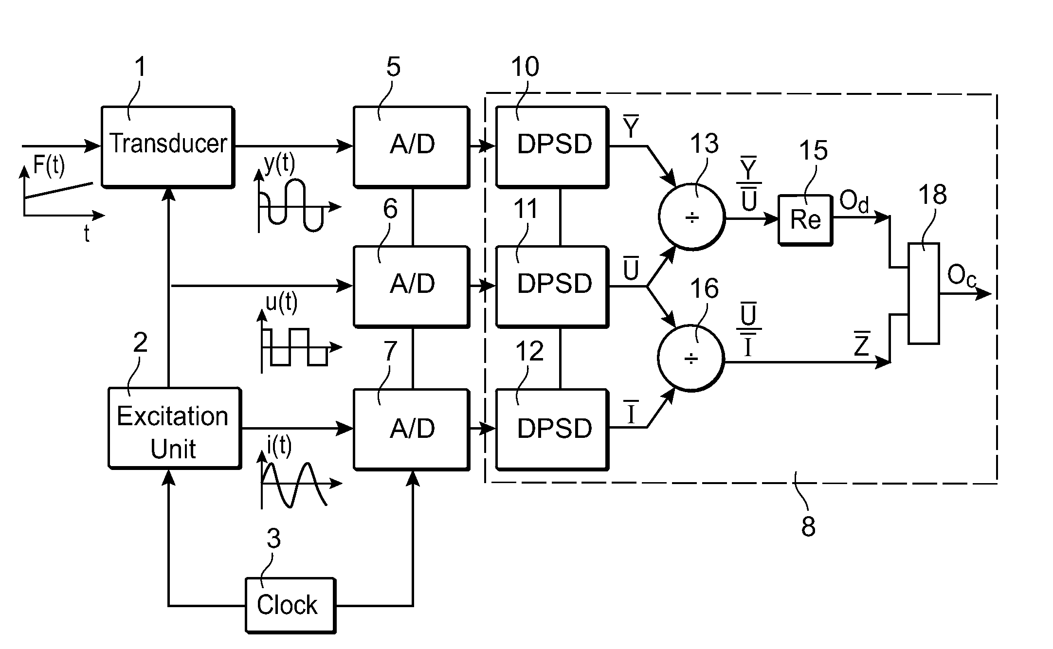
[0042]FIG. 1 illustrates a device for demodulation of an output signal y(t) from a transducer 1 driven by an excitation signal, in the form of a periodic excitation voltage u(t), from an excitation unit 2. For example, the transducer is a magnetoelastic transducer measuring changes in applied force. A time-dependent force F(t) is applied to the transducer 1, which is excited by the excitation voltage u(t) from the excitation unit 2. In FIG. 1 the excitation voltage is depicted as a square wave u(t). The transducer 1 modifies the excitation voltage in dependence on the magnitude of the force F(t), and produces a transducer output signal y(t). The excitation current i(t) is measured by the excitation unit 2. A clock 3 determines the excitation frequency of the excitation unit 2.

[0043]The device comprises a first sampling unit 5 adapted to sample the output signal y(t) from the transducer 1, a second sampling unit 6 adapted to sample the excitation voltage u(t) of the excitation unit, ...


PUM


Abstract

A method and device are provided for demodulation of an output signal from a transducer (1) driven by an alternating excitation signal having an excitation frequency. The transducer produces an amplitude-modulated output signal (y(t)) containing the quantity to be measured. The device has sampling units (5,6,7) to sample the output signal from the transducer and the output signal from the excitation unit, and a computation unit (8) to compute a first complex valued quantity ( Y) including information on the amplitude and phase of the output signal at the excitation frequency based on sampled values of the output signal from the transducer, compute a second complex valued quantity (Ū, Ī) including information on the amplitude and phase of the excitation signal at the excitation frequency based on sampled values of the excitation signal, forming a complex valued output quotient between the first and second complex valued quantities, and compute the demodulated output signal (Od) based on the output quotient.

Description

FIELD OF THE INVENTION[0001]The present invention relates to a device and a method for demodulating an output signal from a transducer driven by an alternating excitation signal having an excitation frequency, which transducer produces an amplitude modulated output signal containing the quantity to be measured.[0002]The present invention is useful for any type of measuring device including a transducer, which produces an amplitude-modulated output signal containing a quantity to be measured, and an excitation unit, which produces an excitation signal for driving the transducer. The transducer is, for example, a differential transformer, a magnetoelastic sensor, or a strain gauge, and the quantity to be measured is, for example, position, stress, force, or torque.PRIOR ART[0003]In order to detect the measured quantity, the output signal from the transducer has to be demodulated. The traditional way to demodulate the output signal of a transducer, for example a magnetoelastic transduc...

Claims


Application Information

Patent Timeline
IPC IPC(8): H03D3/00
CPCG01D1/16G01D21/00G01L1/125G01R19/2506G01R35/005
Inventor NILSSON, JANSOBEL, JARL R.
Owner ABB (SCHWEIZ) AG
Why Eureka
Try Eureka