
Hybrid Feedback Controlled Oscillation Modulator and Switching Power Amplifier System

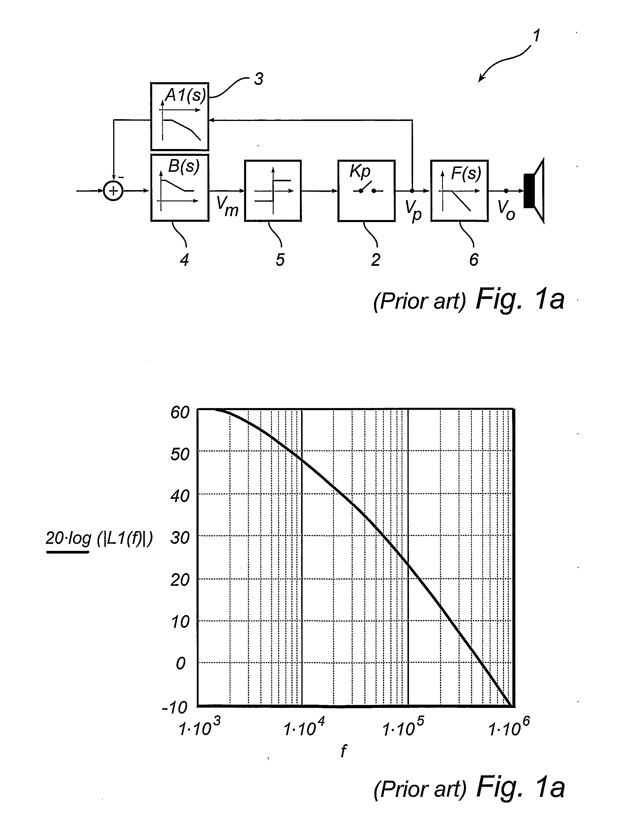
a technology of oscillation modulator and switching power amplifier, which is applied in the direction of amplifiers, amplifiers with semiconductor devices/discharge tubes, electric devices, etc., can solve the problems of amplifiers that cannot perform optimally, amplifiers that need to meet extreme test bench situations, and can not design one control system performing optimal in both states, etc., to achieve simple topological architecture and wide bandwidth error compensation. , the effect of wide bandwidth

Active Publication Date: 2010-11-04
BANG & OLUFSEN ICEPOWER GI
View PDF2 Cites 1 Cited by
  • Summary
  • Abstract
  • Description
  • Claims
  • Application Information

AI Technical Summary

Benefits of technology

[0015]Accordingly, an object of the invention is to provide a new oscillating modulator, the Hybrid feedback Controlled Oscillation Modulator (HCOM), with particular relevance in switching Class D amplifiers, that provides enhanced wide bandwidth error compensation both local both power stage, power supply and local to filter related errors, with a simpler topological architecture that prior art.
[0016]Secondly, an objective of the invention, compared with the applicants own invention WO98 / 19391, is to provide an improved modulator and control system, that provides enhanced stability and unconditioned stable control of the output filter by active means, without the need for excessive feedback differentiation or passive RC filter damping. An objective of the invention is to eliminate the filter transfer function and thus the filter and load dependency from the system transfer function.
[0017]Third, an objective of the invention is to enable enhanced demodulation without the efficiency, stability and performance compromises of prior art, thus improving over all EMI.SUMMARY OF THE INVENTION
[0020]In one preferred embodiment of the invention the 1st feedback path has a low pass filter characteristic, and the 2nd feedback path from the amplifier output a phase lead characteristic, both feedback path weighted such that the local feedback path has a significantly higher attenuation that the global feedback path. In this preferred embodiment the forward path lag compensation filter is implemented to maximize effective loop transfer function gain within the target frequency band and provide well conditions modulation signal characteristics. This simple topology, new to the art, is realizable with only a single operational amplifier in combination with single ended output stages. This first embodiment of the invention offers a range of advantages new to the art, in terms of simplification, robust stability and increased overall performance.
[0022]Further embodiments concern further performance improvement, by the addition of a 3rd feedback loop feedback loop from amplifier output and feeding this to a 2nd preamplifier stage, order to implement higher order control system and full flexibility in amplifier design, further increasing performance.
[0023]A further embodiment of the invention concerns the implementation of the HCOM output filter utilizing filter resonance and natural frequency optimization for both performance, efficiency improvement, and in particular improvement of overall demodulation and thereby EMI performance.

Problems solved by technology

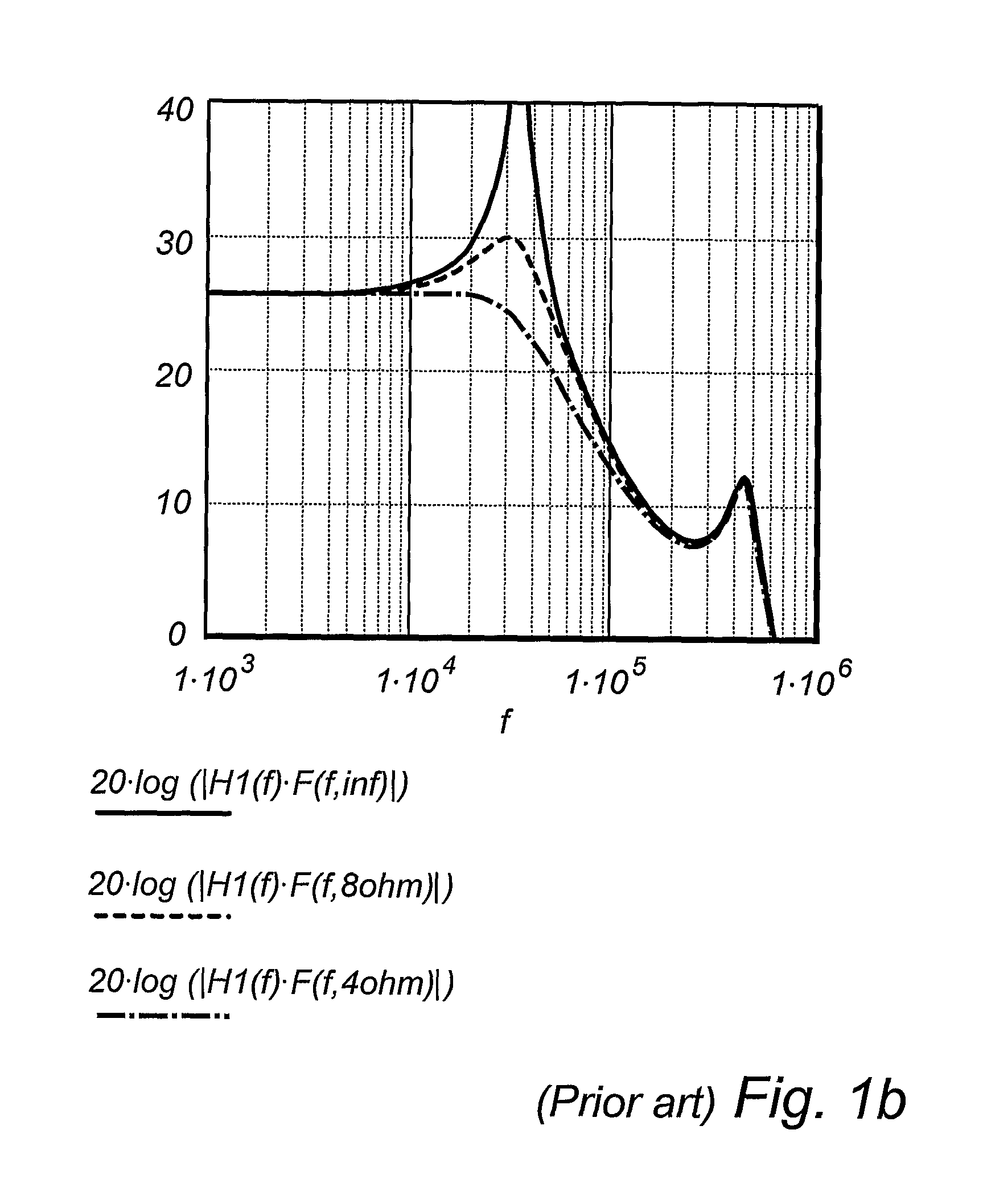
Furthermore, amplifiers need to comply with extreme test bench situations.
It is quite challenging to design one control system performing optimal in both states.
In general, compromises needs to be taken between performance and stability, resulting in that the amplifier actually will not perform optimal in any of the two states, but deliver compromised performance in the both states.

Method used


Image

  • Hybrid Feedback Controlled Oscillation Modulator and Switching Power Amplifier System
  • Hybrid Feedback Controlled Oscillation Modulator and Switching Power Amplifier System
  • Hybrid Feedback Controlled Oscillation Modulator and Switching Power Amplifier System

Examples


first embodiment

of the Invention

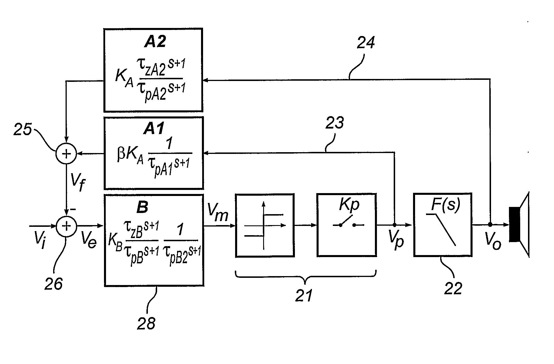
[0057]FIG. 3 illustrates the first preferred embodiment of the invention, the generic Hybrid Controlled Oscillation Modulator HCOM.

[0058]The central pulse modulator and switching power stage have been simplified to a system gain block 11, with transfer function Kp(s), consisting of the equivalent modulator and power stage averaged gain Kp and the total propagation delay of comparator, drive and power stage, tpd:

Kp(s)=Kp·e−tpd·s

[0059]Note that the comparator may be of a non-hysteresis or hysteresis type in terms of e.g. a Schmitt trigger. The objectives of the invention are related to the state feedback architecture introduced in the following, and this can be applied on a range pulse modulator methods, as long as the resulting implementation can be expressed by an equivalent averaged gain and delay as defined above.

[0060]The pulse modulator, power stage and a filter 12, with transfer function F(s), is enclosed by state feedback architecture, consisting of a 1st loca...


PUM


Abstract

A Hybrid feedback Controlled Oscillation Modulator (HCOM) is disclosed, having a 1st feedback path from the output voltage of the switching stage and a second feedback path from the filter output, the two feedback paths being superposed to provide a weighted state feedback signal. The state feedback path signal is subtracted from the input signal to form an error signal, the error signal filtered by a forward path compensation block B(s), closing the loop by feeding the pulse modulator, the loop having a transfer function such that self-oscillation can be established in the closed loop system. In an example embodiment, the first feedback path has a low pass characteristic and the second feedback path lead characteristic, the first feedback path being weighted by a weighting factor 55. Further embodiments include a pure passive realization without a forward path device and the application of 3rd feedback loops to enhance global amplifier performance.

Description

FIELD OF THE INVENTION[0001]This invention relates to the field of DC-DC and DC-AC power conversion, with particular relevance within high definition switching audio power amplification.BACKGROUND OF THE INVENTION[0002]Switching Class D audio amplifiers have found increasing use in the industry in recent years, due to the improvements in output stage switching devices and equally modulation and feedback control methods. The classical switching power amplifier system consists of the pulse modulator, converting an analog or digital source into a pulse modulated signal, following amplified by a switching power stage. A passive demodulation filter reproduces the power modulated power signal.[0003]Most switching class D amplifiers are based on variants of Pulse Width Modulation. The challenges in switching amplifier design relate to:[0004]PWM is in effect a multiplication / mixing between the input and power supply variable. This is equivalent to zero power supply rejection.[0005]The switc...

Claims


Application Information

Patent Timeline
Patent Type & Authority Applications(United States)
IPC IPC(8): H03F3/217
CPCH03F2200/03H03F3/217H03F3/38
Inventor NIELSEN, KARSTENLJUSEV, PETER
Owner BANG & OLUFSEN ICEPOWER GI
Learn More