Devices, systems and methods for creating and demodulating orbital angular momentum in electromagnetic waves and signals

a technology of electromagnetic waves and electromagnetic waves, applied in nanotechnology, instruments, nanotechnology, etc., can solve the problems of random and uncontrolled atmospheric turbulence or distortion, aberrations or other perturbations, and the ability to improve the demodulation effect of oam beams, reduce multiplexing errors, and mitigate interference between multiple oam beams

Active Publication Date: 2021-03-09
THE RES FOUND FOR SUNY
View PDF7 Cites 0 Cited by
  • Summary
  • Abstract
  • Description
  • Claims
  • Application Information

AI Technical Summary

Benefits of technology

[0055]Furthermore, the invention may have one or more layers, and in multiple layer configurations, top and bottom impedance matching layers minimize reflection energy losses and enable high efficiency generation of OAM modulated waves without phase distortion. The design incorporates variable sizes of perforated unit cells and may employ perforated or solid matched layers depending upon the requirement of accurate impedance matching, and the flat disc shape of the phase plate provides the advantage of being compact and easy to install.
[0064]In addition, the array of holes can be made in such a way that the FPP can be used to generate diffractive as well as non-diffractive OAM beams as the output, with spherical or near spherical wave front, parallel wave front or any other shaped EM beams as input. Additional lenses are not necessary to focus the beam, e.g., for near-field scanning optical microscopy. Further, non-diffracting OAM beams decrease and mitigate interference between multiple OAM beams, reduce multiplexing errors, and improve OAM demodulation by reducing the need for back-end signal processing software.

Problems solved by technology

Due to this demand wireless communication systems face serious challenges to improve data transmission as the allowed spectrum and signal polarization are limited even after adopting high density coding and channel sharing techniques.
However, FSO also suffers from several major drawbacks, including absorption of the laser beam by the intervening medium and also the effects of random and uncontrolled atmospheric turbulence or distortions, aberrations or other perturbations upon the optical beam wavefront.
These effects are undesirable as they result in variations in the beam intensity profile, degradation of the signal, inaccuracies in the receiving station and reduced throughput of the communications channel.
Free space EM beam communications may also fail to protect privacy if when confidential data are transmitted by a sender to an intended recipient and a third party is capable of intercepting the EM beam and decoding the confidential data.
However, these modes can only offer limited channels in a communication system.
Increasing the bandwidth of the channel may in some cases, however, face technical obstacles.
However, the generation of OAM modulated beams at millimeter wave frequencies is challenging due to both noise caused by the interference of propagating waves having different phases and issues with manufacturing.
However, these aforementioned components generally lack the compactness, flat surfaces, perfect impedance matching and ease of manufacturing, and the latter component is narrow band, difficult to fabricate and results in OAM mode distortion.
However, this design leads to bulky OAM phase plate.
Further, previously developed planar phase plates typically require many different layers or require holes of different diameters, each of which make manufacture more challenging.
In addition, for the non-planar spiral phase plate having abrupt surfaces of different heights or thicknesses, this results in a bulkier phase plate device.
Both the reflectors used are metallic and work on reflective principle, which has the disadvantages of off-set feed and source blockage.
The system is also not compact and the manufacturing process of parabolic reflectors is not economical.
The system is not compact and the manufacturing process of such reflectors is costly.
The proposed design is flat and compact but provides a highly distorted phase and due to the use of metallic patches the loss factor is high.
It is expensive and time consuming to fabricate such a device with different hole diameters.
Another drawback of the design lies with the abrupt stepped surface, which is bulky and undesirable.
The use of metallic patches introduces ohmic losses and phase distortion is also an issue.
Matching issues are not addressed in this patent and it is also mechanized with moving parts that may fail or are prone to mechanical error.
In the case of the tunable meta-material lens, phase distortion may occur due to multiple lumped elements present in the vicinity of the lens.
However, many of these inventions just discussed utilize meta-materials, usually including metallic patches that create distortion, losses and narrow bandwidth.
In addition, many of these inventions employ complicated methods of manufacture and the resulting devices are either bulky, not compact or non-planar.
However, such EM beams, especially laser beams at optical frequencies carrying multiple OAM states, can be severely affected by the presence of aberrations in the medium through which they travel.
The demand for more advanced tactical equipment has increased as older equipment require a large number of vehicles to transport, which limits their deployment flexibility.
Furthermore, the bandwidth within which this equipment operates is unable to adequately meet the demand for modern network enabled applications.
The concept is also applicable across the EM spectrum, including X-Ray and Gamma-Ray frequencies, but current methods of manufacture are not capable of creating a device based the current concept and operable at those frequencies.

Method used


Image

  • Devices, systems and methods for creating and demodulating orbital angular momentum in electromagnetic waves and signals
  • Devices, systems and methods for creating and demodulating orbital angular momentum in electromagnetic waves and signals
  • Devices, systems and methods for creating and demodulating orbital angular momentum in electromagnetic waves and signals

Examples


Embodiment Construction

[0081]These, and other, aspects and objects of the present invention will be better appreciated and understood when considered in conjunction with the following description and the accompanying drawings. It should be understood, however, that the following description, while indicating preferred embodiments of the present invention and numerous specific details thereof, is given by way of illustration and not of limitation. Many changes and modifications may be made within the scope of the present invention without departing from the spirit thereof and the invention includes all such modifications, such as, but not limited to, the use of this invention to generate and transmit Orbital Angular Momentum (OAM) electromagnetic (EM) waves.

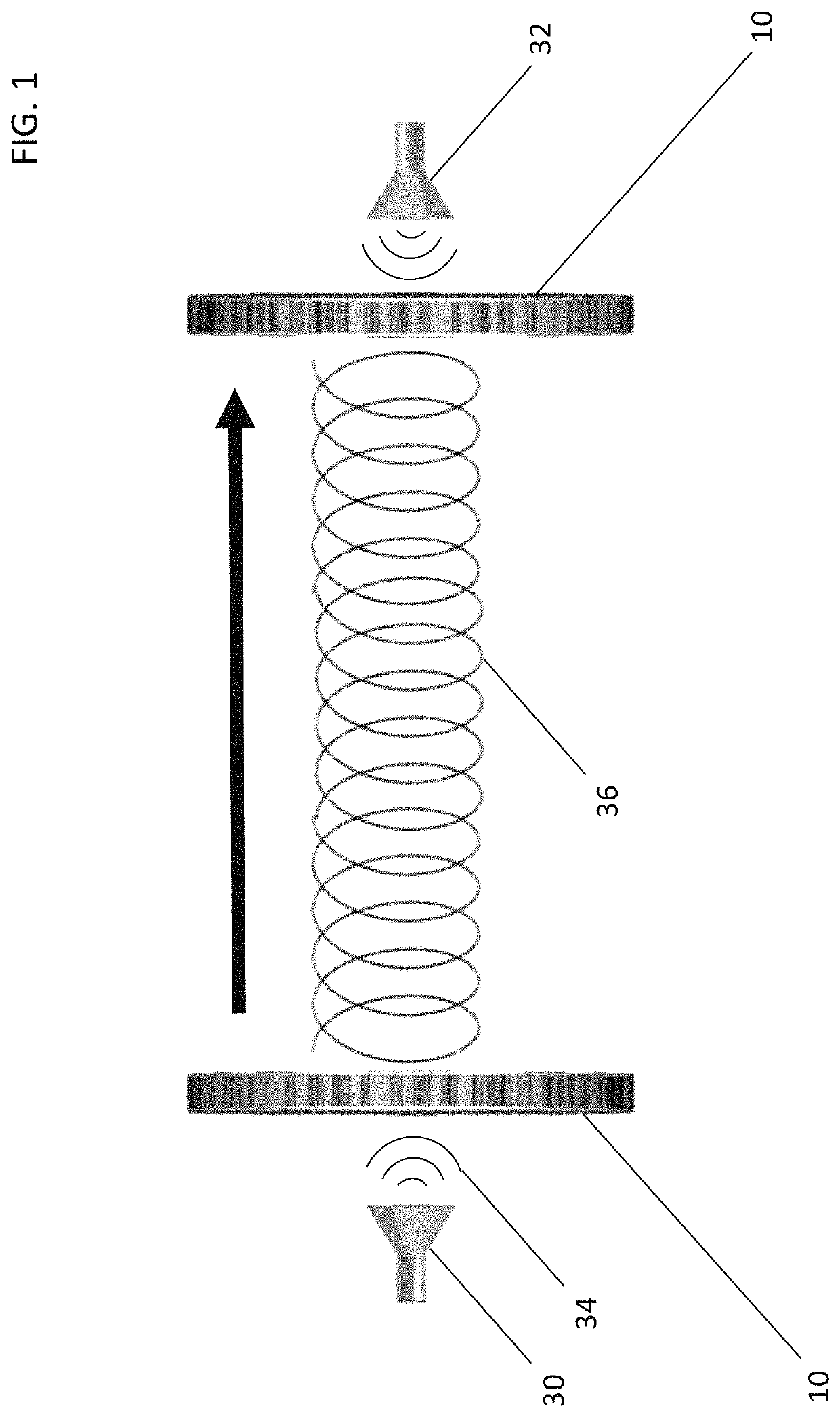
[0082]OAM signals are of particular importance in telecommunications systems. OAM telecom systems include a transmitter system capable of generating and sending OAM modulated signals to a receiver system capable of demodulating the OAM signals to extrac...


PUM


Abstract

Orbital angular momentum (OAM) communications systems provide an additional degree of freedom to the electromagnetic waves that travel between the transmission and receiving stations, thereby enabling a dramatic increase in data transmission rates. The present invention provides a design for a very low reflectivity flat spiral phase plate that generates OAM modes and a method of making the same. The design incorporates variable sizes of perforated unit cells and may include matched layers to provide improved impedance matching, and the flat disc shape makes the phase plate compact and easy to install. The OAM phase plate can be designed to operate at frequencies from a few 100s KHz to ultraviolet frequencies and is capable of providing one or more OAM modes at the operational frequencies, irrespective of polarization. In a preferred embodiment, the OAM phase plate is designed for operation at about 30 GHz frequency, with 20 GHz bandwidth.

Description

RELATED APPLICATIONS[0001]This application claims priority to U.S. Provisional Application No. 62 / 481,119, filed Apr. 4, 2017 and entitled DEVICES, SYSTEMS AND METHODS FOR CREATING AND DEMODULATING ORBITAL ANGULAR MOMENTUM IN ELECTROMAGNETIC WAVES AND SIGNALS.BACKGROUND1. Field[0002]One or more aspects of the present invention relate to the transmission and reception of data using beams of electromagnetic waves, and more particularly to devices, systems and methods for transmitting data with photons in different states of orbital angular momentum (OAM). Specifically, this application for patent discloses and claims an arrangement of transmitting and receiving antennas, modulators and filters as well as radio, optical or other free space connections employing such arrangements, and also related methods of modulating, demodulating and multiplexing signals across such systems.2. Description of Related Art[0003]The demand for higher data rates and secure communications has been constant...

Claims


Application Information

Patent Timeline
Patent Type & Authority Patents(United States)
IPC IPC(8): H01Q15/10H01Q15/02H01Q13/02G02B5/00B82Y20/00
CPCH01Q15/02G02B5/00H01Q13/02H01Q15/10B82Y20/00G02B5/3083
Inventor PATRI, ASHUTOSHPARIMI, PATANJALI V.KOLACKI, MICHAEL
Owner THE RES FOUND FOR SUNY
Why Eureka
Try Eureka