Fuel injector

a fuel injector and fuel technology, applied in the direction of machines/engines, mechanical equipment, lighting and heating apparatus, etc., can solve the problems of high combustion temperature, high combustion rate, and large amount of combustion air, and achieve the effect of reducing the expansion of the fuel stream and simple passage geometries

Active Publication Date: 2010-05-13
ROLLS ROYCE PLC
View PDF13 Cites 15 Cited by
  • Summary
  • Abstract
  • Description
  • Claims
  • Application Information

AI Technical Summary

Benefits of technology

[0027]Preferably, the pressure surface is absent from the second section. This can help to discourage expansion of the fuel stream, which might otherwise tend to counter the Coand{hacek over (a)} effect.
[0028]The flow passage may be a cylindrical annulus. Alternatively, the flow passage may be a frustoconical annulus which expands from the fuel distributor slots to the prefilming lip. Configuring the fuel distribut

Problems solved by technology

Efficient mixing of air and fuel results in higher combustion rates.
To achieve lean burn, the system not only incorporates pilot and mains fuel injectors, but also requires a relatively large amount of combustion air.
Non-uniform mixing prior to combust

Method used


Image

  • Fuel injector
  • Fuel injector
  • Fuel injector

Examples


Embodiment Construction

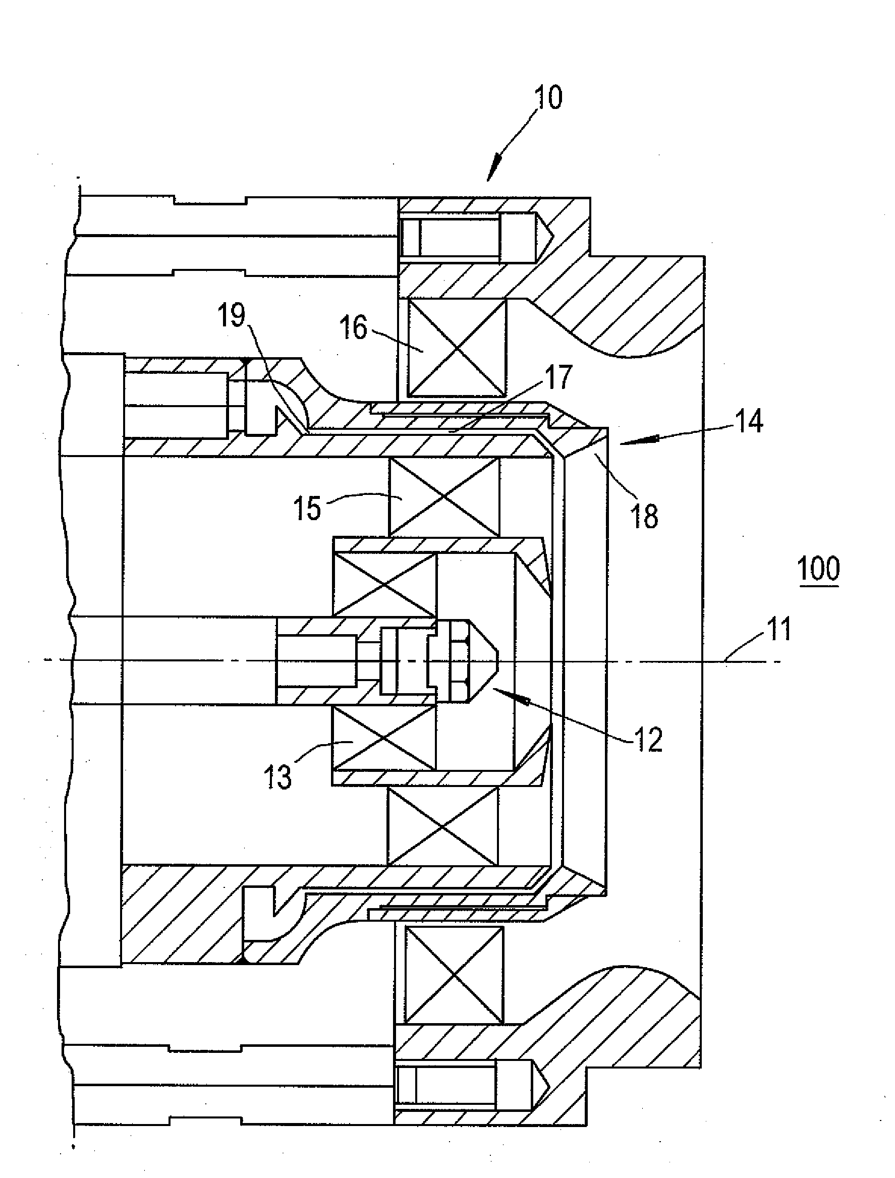
[0041]Before discussing the invention it is helpful to provide more detail of other fuel injector arrangements.

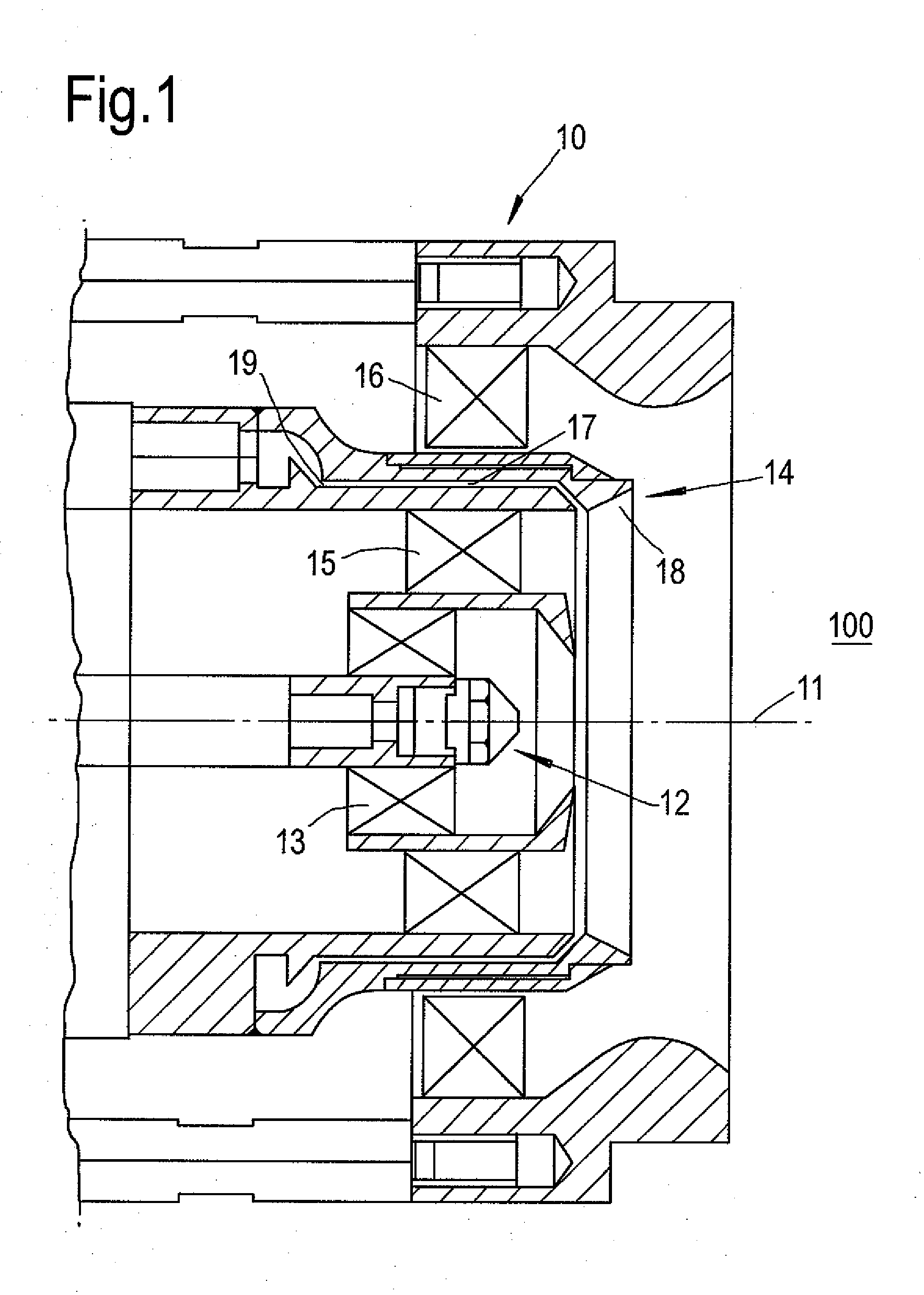
[0042]The mains fuel injector of a pilot and mains fuel nozzle passes typically 85% of the fuel and air, and is thus the dominant emissions source. In a fuel injection nozzle such as that shown in FIG. 1, a relatively large diameter mains fuel prefilming lip, and correspondingly large annular flow passage (gallery), is generally needed to deliver such a high percentage of the fuel and air. The large diameter can result in a correspondingly wide spacing of the fuel distributer slots which deliver fuel to the fore end of the gallery. For example, the fuel slot pitch to width ratio in the circumferential direction may be 30:1. In the gallery, the fuel streams delivered by the distributor slots spread sideways. Desirably, the spread should be enough to fill the annulus circumferentially, and hence create a circumferentially uniform mass flow rate onto the prefilming lip, as req...


PUM


Abstract

A fuel injector for a fuel spray nozzle of a gas turbine engine combustor is provided. The fuel injector has an annular flow passage which conveys fuel to a prefilming lip at an end of the flow passage. The fuel injector also has plurality of fuel distributor slots which are circumferentially spaced around and in fluid communication with the other end of the flow passage to deliver respective fuel streams into the flow passage. The slots are configured so that the fuel streams enter the flow passage at a swirl angle of at least 80° relative to the axis of the flow passage.

Description

CROSS REFERENCE TO RELATED APPLICATION[0001]This application is entitled to the benefit of British Patent Application No. GB 0820560.1, filed on Nov. 11, 2008.FIELD OF THE INVENTION[0002]The present invention relates to a fuel injector for a fuel spray nozzle of a gas turbine engine combustor.BACKGROUND OF THE INVENTION[0003]Fuel injection systems deliver fuel to the combustion chamber of an engine, where the fuel is mixed with air before combustion. One form of fuel injection system known in the art is a fuel spray nozzle. Fuel spray nozzles atomise the fuel to ensure its rapid evaporation and burning when mixed with air.[0004]An airblast atomiser nozzle is a type of fuel spray nozzle in which fuel delivered to the combustion chamber by a fuel injector is aerated by swirlers to ensure rapid mixing of fuel and air, and to create a finely atomised fuel spray.[0005]Efficient mixing of air and fuel results in higher combustion rates. It also reduces unburnt hydrocarbons and exhaust smo...

Claims


Application Information

Patent Timeline
IPC IPC(8): F02C7/22B05B7/10
CPCF23D11/383F23D2900/11101
Inventor TOON, IAN JAMES
Owner ROLLS ROYCE PLC
Why Eureka
Try Eureka