Near field light generating device, optically assisted magnetic recording head, optically assisted magnetic recording device, near field optical microscope and near field light exposure apparatus

a technology of optically assisted magnetic recording and recording head, which is applied in the direction of lighting and heating apparatus, applications, instruments, etc., can solve the problems of increasing the magnetic field required for recording, affecting the quality of the material, so as to achieve high efficiency

Inactive Publication Date: 2010-05-13
KONICA MINOLTA OPTO
View PDF6 Cites 12 Cited by
  • Summary
  • Abstract
  • Description
  • Claims
  • Application Information

AI Technical Summary

Benefits of technology

[0052]According to the present invention, a second medium layer having a refractive index lower than that of a first medium layer is stacked onto the first medium layer for outputting the condensed light, and a plasmon probe is formed on the second medium layer. This arrangement ensures generation of near field light at high efficiency.

Problems solved by technology

In a magnetic recording method, an increase in the recording density causes the magnetic bit to be seriously susceptible to external temperature and other factors.
However, use of such a recording medium, in turn, increases the magnetic field required for recording.
This value, however, has already come very close to the limit of material, and a drastic increase cannot be expected.
Further, a heating device is not allowed to be in contact with a recording medium.
In the normal optical system, condensation of light cannot be performed to meet this requirement, because of the presence of a diffraction limit.

Method used


Image

  • Near field light generating device, optically assisted magnetic recording head, optically assisted magnetic recording device, near field optical microscope and near field light exposure apparatus
  • Near field light generating device, optically assisted magnetic recording head, optically assisted magnetic recording device, near field optical microscope and near field light exposure apparatus
  • Near field light generating device, optically assisted magnetic recording head, optically assisted magnetic recording device, near field optical microscope and near field light exposure apparatus

Examples


example 1

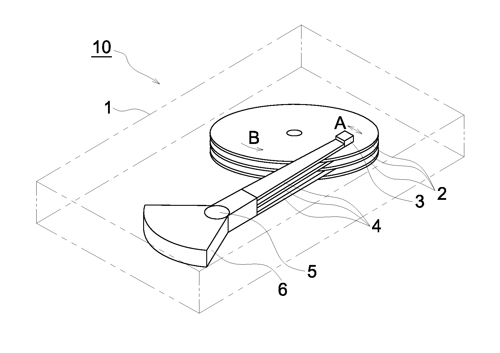
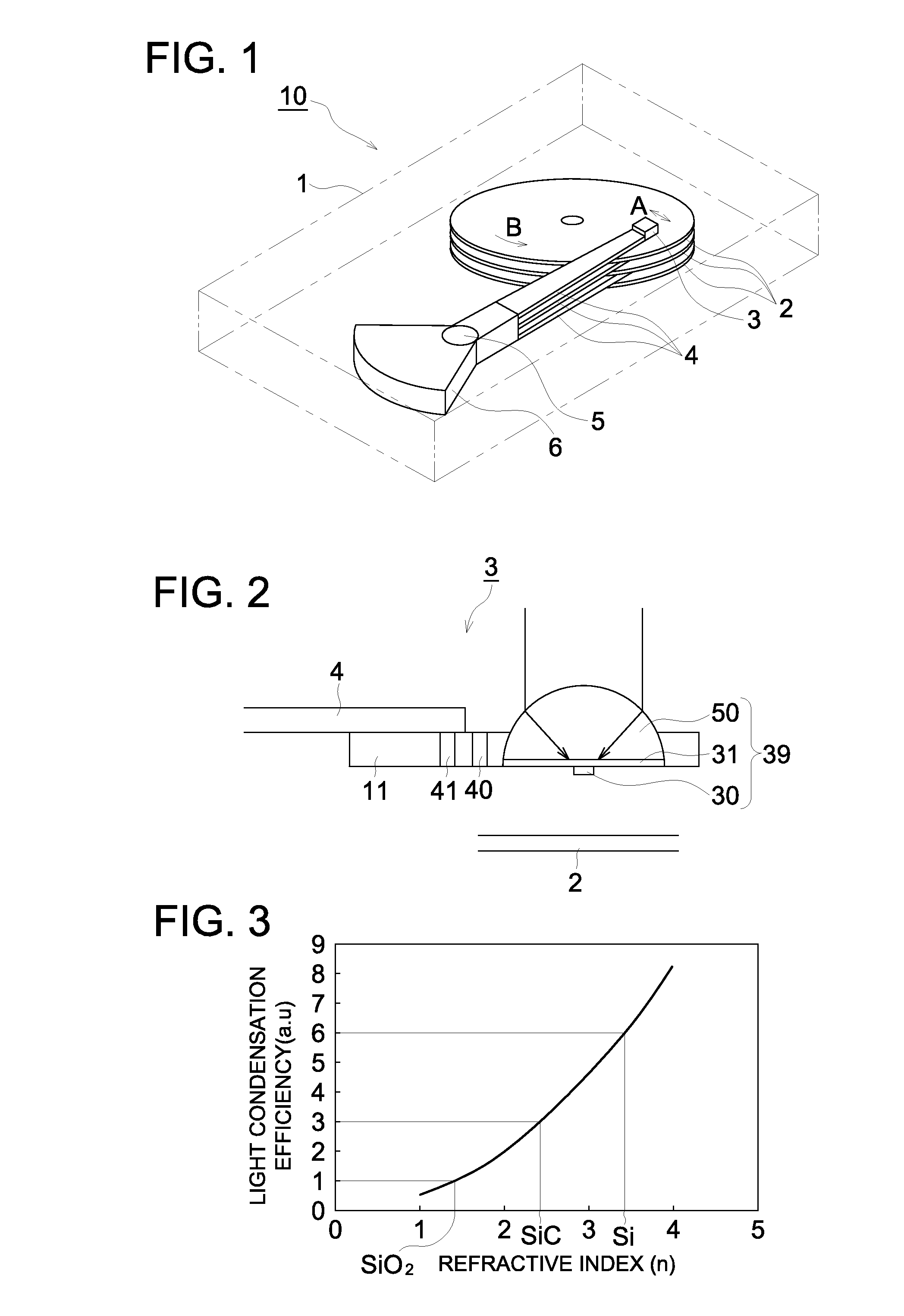
[0162]In Example 1, the SILs 50, with the buffer layers 31 of different thicknesses, used in the near field light generating device 39 in the first embodiment shown in FIG. 2 were made. Further, the optically assisted magnetic recording heads 3 of the first embodiment were made each using the above-obtained near field light generating device 39 to verify that a sufficient amount of near field light for magnetic recording was generated.

[0163]The following describes the steps of manufacturing the near field light generating device 39.

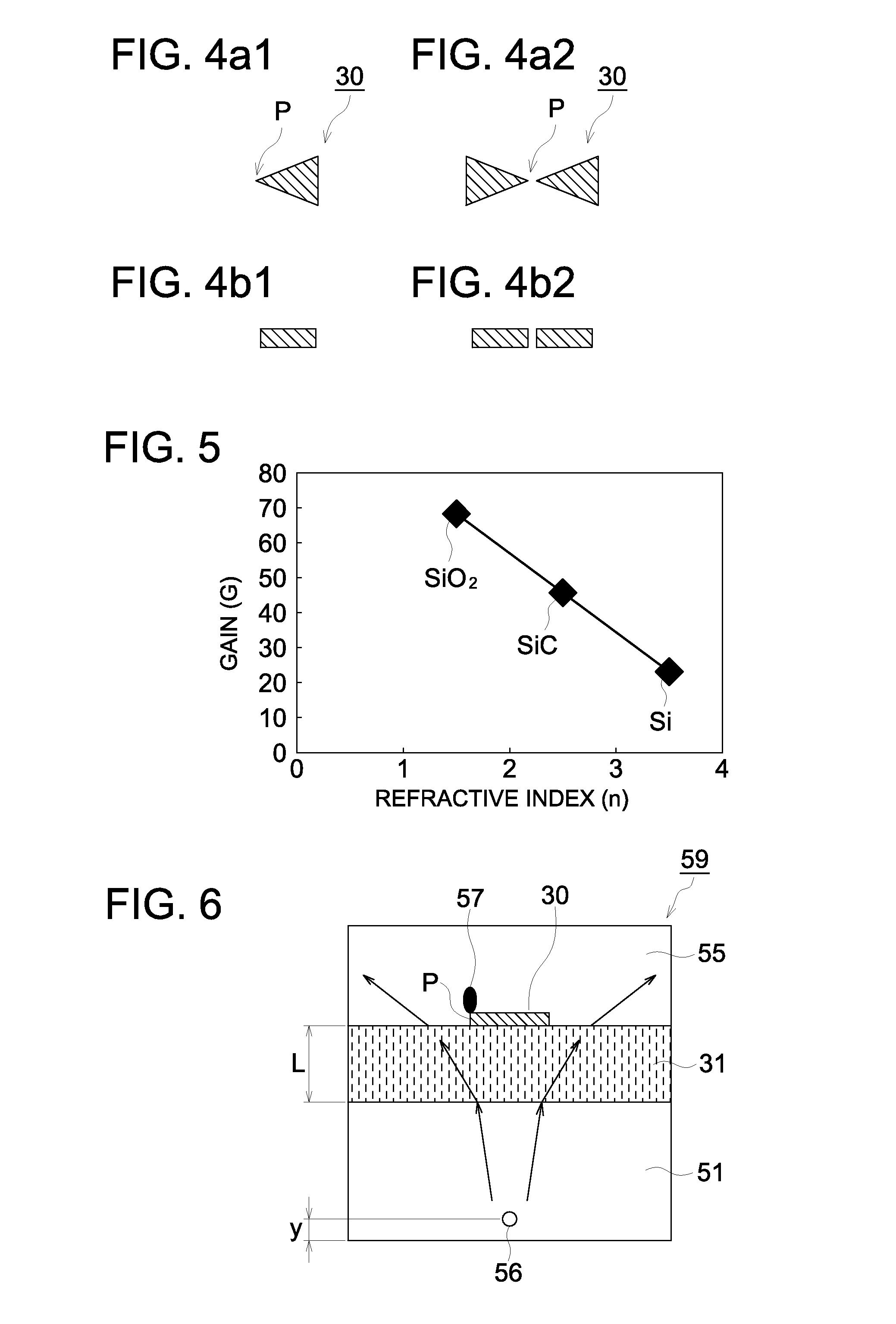
[0164]First, eight SILs 50 to be used in the near field light generating devices 39 were made of silicon crystal. Each SIL 50 has a curvature radius of 1.4 mm. Then buffer layers 31 each having a thickness of 50, 100, 250, 500, 1000 or 2000 nm were formed on the plane surfaces of the six SILs 50. The buffer layers 31 were formed on the plane surfaces of the SILs 50 using the CVD (chemical vapor deposition) method using the TEOS (tetraethoxysilane) as mate...

example 2

[0177]In Example 2, the SILs 50 were made of GaAsP and the buffer layer 31 was made of GaF with different thicknesses, by the same process as Example 1. Further, the optically assisted magnetic recording heads 3 of the first embodiment were made each using the above-obtained near field light generating device 39 to verify that a sufficient amount of near field light for magnetic recording was generated.

[0178]The steps of manufacturing the near field light generating device 39 are the same as Example 1, and detailed description will be omitted.

[0179]Similarly to the case of the above-mentioned Example, the buffer layers 31 having thicknesses L of 50, 100, 250, 500, 1000 and 2000 nm were formed on the plane surface of the SILs 50. A gold plasmon probe having a thickness of 40 nm was formed on each buffer layer 31 of the SIL 50 by the same steps as Example 1. As a comparative example, on of the SILs 50 without buffer layers 31, a gold plasmon probe in the same shape was made.

[0180]The ...

example 3

[0192]In Example 3, the SILs 50 of FIG. 9 with the buffer layers 31 formed, by the steam oxidation method, each to have different thickness. Further, the optically assisted magnetic recording heads 3 were made each using the above-obtained near field light generating device 39 to verify that a sufficient amount of near field light for magnetic recording was generated.

[0193]The following describes the steps of manufacturing the near field light generating device 39.

[0194]First, eight SILs 50 to be used in the near field light generating devices 39 were made of silicon crystal. Each SIL 50 has a curvature radius of 1.4 mm. Then buffer layers 31 each having a thickness of 50, 100, 250, 500, 1000 or 2000 nm were formed on the plane surfaces of the six SILs 50. The buffer layers 31 were made by putting the silicon-made SIL 50 in a vapor atmosphere and forming oxide films (SiO2) on the whole surface of each SIL 50.

[0195]A Gold film was formed on each buffer layer 31 of six SILs 50 by the ...


PUM

PropertyMeasurementUnit
diameteraaaaaaaaaa
refractive indexaaaaaaaaaa
near field light microscopeaaaaaaaaaa

Abstract

Disclosed is a near field light generating device comprising a first medium layer which transmits light from a light source. This near field light generating device generates near field light by using light irradiating a plasmon probe through the first medium. This near field light generating device is characterized in that a second medium layer having a refractive index lower than that of the first medium layer is formed between the first medium layer and the plasmon probe.

Description

FIELD OF THE INVENTION[0001]The present invention relates to a near field light generating device, an optically assisted magnetic recording head, an optically assisted magnetic recording device, a near field optical microscope and a near field light exposure apparatus.BACKGROUND OF THE INVENTION[0002]In a magnetic recording method, an increase in the recording density causes the magnetic bit to be seriously susceptible to external temperature and other factors. This requires use of a recording medium having a greater coercive force. However, use of such a recording medium, in turn, increases the magnetic field required for recording. The maximum of the magnetic field generated by the recording head is determined by the saturation magnetic flux density. This value, however, has already come very close to the limit of material, and a drastic increase cannot be expected. A solution to this problem is proposed in a technique wherein magnetic weakening is caused by local heating at the t...

Claims


Application Information

Patent Timeline
Patent Type & Authority Applications(United States)
IPC IPC(8): G11B11/00G01N21/47G02B6/00
CPCB82Y10/00B82Y20/00G01Q60/22G01Q80/00G11B2005/0021G11B7/124G11B7/1387G11B9/1409G11B2005/001G11B5/314
Inventor NISHIDA, NAOKIKONNO, KENJI
Owner KONICA MINOLTA OPTO
Why Eureka
Try Eureka