Ferritic stainless steel and steel sheet for heat pipes, and heat pipe and high-temperature exhaust heat recovery system

a technology of ferritic stainless steel and heat pipes, which is applied in the direction of indirect heat exchangers, lighting and heating apparatus, etc., can solve the problems of reducing the heat transfer affecting the efficiency of cooling water, etc., and achieves low cost and high popularity.

Inactive Publication Date: 2010-05-20
DENSO CORP +1
View PDF17 Cites 24 Cited by
  • Summary
  • Abstract
  • Description
  • Claims
  • Application Information

AI Technical Summary

Benefits of technology

[0021]According to the invention, the increase in the inner pressure of a stainless steel-made heat pipe, which is caused by hydrogen generation in the heat pipe and is problematic therein, can be significantly relieved

Problems solved by technology

However, a heat pipe formed of stainless steel may have a large quantity of hydrogen generated inside it in the early stage of driving.
In addition, the hydrogen generation inside the heat pipe is a risk factor of lowering the heat transfer efficiency to cooling water and is additionally a risk factor of impar

Method used


Image

  • Ferritic stainless steel and steel sheet for heat pipes, and heat pipe and high-temperature exhaust heat recovery system
  • Ferritic stainless steel and steel sheet for heat pipes, and heat pipe and high-temperature exhaust heat recovery system
  • Ferritic stainless steel and steel sheet for heat pipes, and heat pipe and high-temperature exhaust heat recovery system

Examples


example 1

[0055]Steels shown in Table 1 (30 kg each) were melt-produced in a vacuum smelting furnace, and hot-rolled, annealed, pickled, cold-rolled and finish-annealed according to an ordinary ferritic stainless steel sheet production method, thereby producing cold-rolled annealed pickled steel materials (sample materials) having a thickness of 1.0 mm, for which the pickling finish was No. 2D as defined in Table 14 in JIS G4305:2005.

TABLE 1Chemical Composition (mas. %)ClassificationNo.CSiMnPSNiCrMoCuNNbTiAlothersSamples ofA10.020.301.000.0250.0020.1118.32.050.180.010.65———the inventionA20.010.190.220.0330.0010.1821.90.980.120.010.270.170.08—A30.010.250.350.0300.0020.1518.21.070.080.010.35———A40.010.220.310.0270.0020.1818.51.010.130.01———Zr: 0.24A50.010.270.420.0310.0010.0818.40.95—0.010.10——V: 0.23A60.010.550.260.0280.0010.0918.5—0.490.020.450.04—Ca: 0.005A70.010.310.220.0210.0030.1120.22.011.520.010.45——W: 1.24A80.020.220.310.0220.0010.0920.50.23—0.010.42——REM: 0.02A90.010.180.250.0290.0010...

example 2

Heating / Cooling Cycle Durability Test

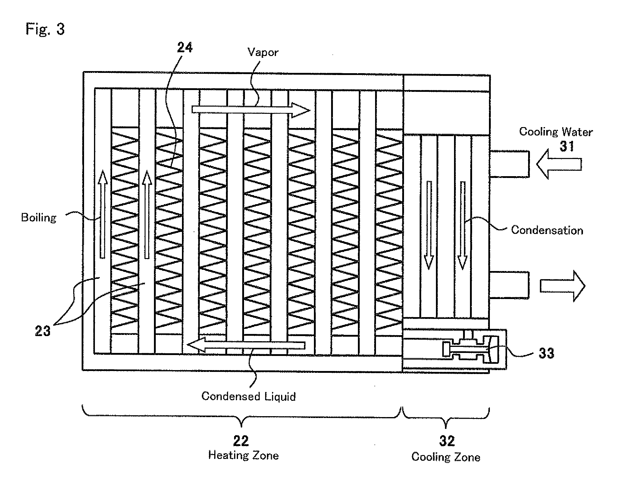
[0070]Using a cold-rolled annealed steel sheet (#400 dry polish-finished steel sheet) having a thickness of 0.8 mm of the samples A1 to A3, B6 and B7 in Table 1, the heat pipe (cup 23) of a high-temperature exhaust heat recovery system as in FIG. 3 was constructed. The heating method employed herein comprises introducing a high-temperature gas into the heat-collecting fin 24 from an external gas burner. The system was exposed to a test of heating / cooling 2000 cycles, in which one cycle comprises “1. heating with coolant (water) circulation for 5 minutes→2. further heating for 5 minutes with coolant circulation stopped→3. coolant circulation and heating stopped for 5 minutes”. The temperature of the heat pipe was about 400° C. in the step 1 of heating with coolant circulation, about 800° C. in the step 2 of heating with coolant circulation stopped, and from 100 to 200° C. in the cooling step 3; and in this cycle, the system is not corroded by dew ...


PUM

PropertyMeasurementUnit
Temperatureaaaaaaaaaa
Fractionaaaaaaaaaa
Fractionaaaaaaaaaa

Abstract

Provided is a ferritic stainless steel for heat pipes of high-temperature exhaust heat recovery systems, which comprises, in terms of % by mass, from 16 to 32% of Cr, at most 0.03% of C, at most 0.03% of N, at most 3% of Si, at most 2% of Mn, at most 0.008% of S, from 0 to 0.3% of Al, and at least one of at most 0.7% of Nb, at most 0.3% of Ti, at most 0.5% of Zr and at most 1% of V, and optionally at least one of at most 3% of Mo, at most 3% of W, at most 3% of Cu, at most 0.1% of Y, at most 0.1% of REM (rare earth metal) and at most 0.01% of Ca, with a balance of Fe and inevitable impurities, and which satisfies at least the following formula (1), formula (2) and formula (5):
Cr+3(Mo+Cu)≧20  (1)
Cr+3(Si+Mn+Al−Ti)≧20  (2)
0.037{(C+N)/(V+Ti+0.5Nb+0.5Zr)}+0.001≦0.01  (5).

Description

BACKGROUND OF THE INVENTION[0001]1. Field of the Invention[0002]The present invention relates to stainless steel and steel sheets for use for heat pipes for heat exchange that harness the latent heat of evaporation of water, as well as to the heat pipe thereof and a high-temperature exhaust heat recovery system comprising it.[0003]2. Background Art[0004]Recently, a high-temperature exhaust heat recovery system is being put into practical use for the purpose of recovering the heat of engine exhaust gas to be discharged at high temperatures in vehicle driving and recycling it as an energy source for vehicles for the purpose of enhancing fuel efficiency in vehicles. In general, a heat exchanger is applied to recovery of exhaust heat, which is for heat exchange between exhaust heat and cooling water or any other heat medium; and as a method of realizing efficient heat exchange, a heat exchanger with a heat-transferring means that may be referred to as a heat pipe is being specifically n...

Claims


Application Information

Patent Timeline
IPC IPC(8): F28D15/00C22C38/18C22C38/50C22C38/44C22C38/46
CPCC21D6/002C21D8/0226C21D8/0236C21D8/0273C22C38/02C22C38/50C22C38/06C22C38/42C22C38/44C22C38/48C22C38/04
Inventor NISHIDA, YUKIHIROFUJIMURA, YOSHITOMOOKU, MANABUMUKOBARA, YUKIKOHARA, KIMIOKAFUKU, KAZUAKI
Owner DENSO CORP
Why Eureka
Try Eureka