Sound source separation system, sound source separation method, and computer program for sound source separation

a sound source and computer program technology, applied in the field of sound source separation systems and sound source separation methods, can solve the problems that the conventional system cannot separate “sound mixtures containing both harmonics", and achieve the effects of preventing the occurrence of erroneous estimation, improving parameter estimation precision, and reducing the cost function

Inactive Publication Date: 2010-05-27
NAT INST OF ADVANCED IND SCI & TECH
View PDF2 Cites 39 Cited by
  • Summary
  • Abstract
  • Description
  • Claims
  • Application Information

AI Technical Summary

Benefits of technology

[0028]The updated model parameter estimation/storage section preferably estimates the parameters using a cost function. Preferably, the cost function is a cost function J defined on the basis of a sum J0 of all of KL divergences J1×α (α is a real number that satisfies 0≦α≦1) between the plurality of power spectrograms at each time stored in the power spectrogram separation/storage section and the plurality of updated power spectrograms at each time stored in the second power spectrogram generation/storage section and KL divergences J2×(1−α) between the plurality of updated power spectrograms at each time stored in the second power spectrogram generation/storage section and the plurality of initial power spectrograms at each time stored in the first power spectrogram generation/storage section, and used each time the power spectrogram separation/storage section performs the separation process, for example. The plurality of parameters respectively contained in the plurality of updated model parameters are estimated to minimize the cost function. The updated model parameter estimation/storage section is configured to in

Problems solved by technology

Therefore, the conventional system cannot separate “sound mixtures containing both harmonic-st

Method used


Image

  • Sound source separation system, sound source separation method, and computer program for sound source separation
  • Sound source separation system, sound source separation method, and computer program for sound source separation
  • Sound source separation system, sound source separation method, and computer program for sound source separation

Examples


Embodiment Construction

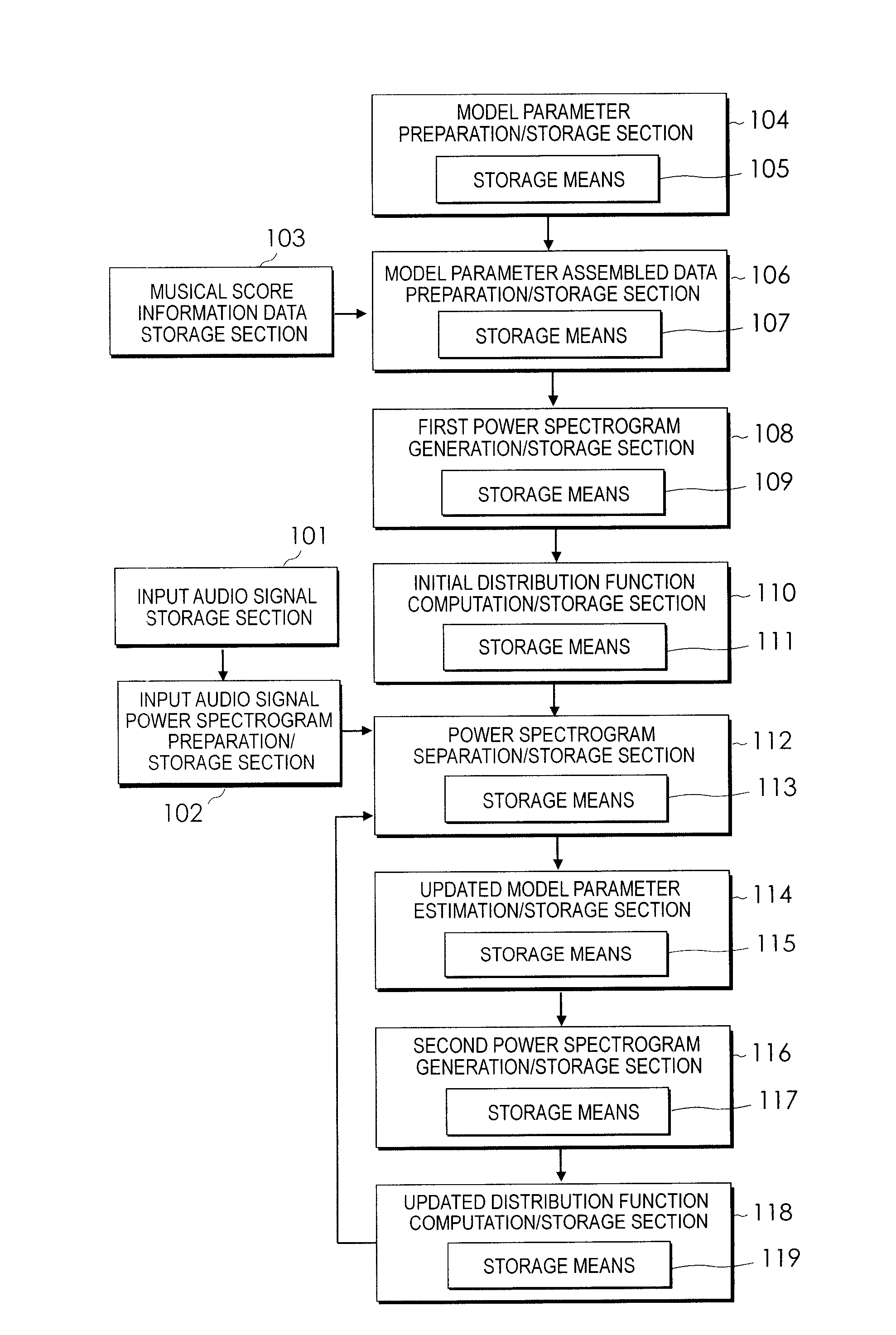
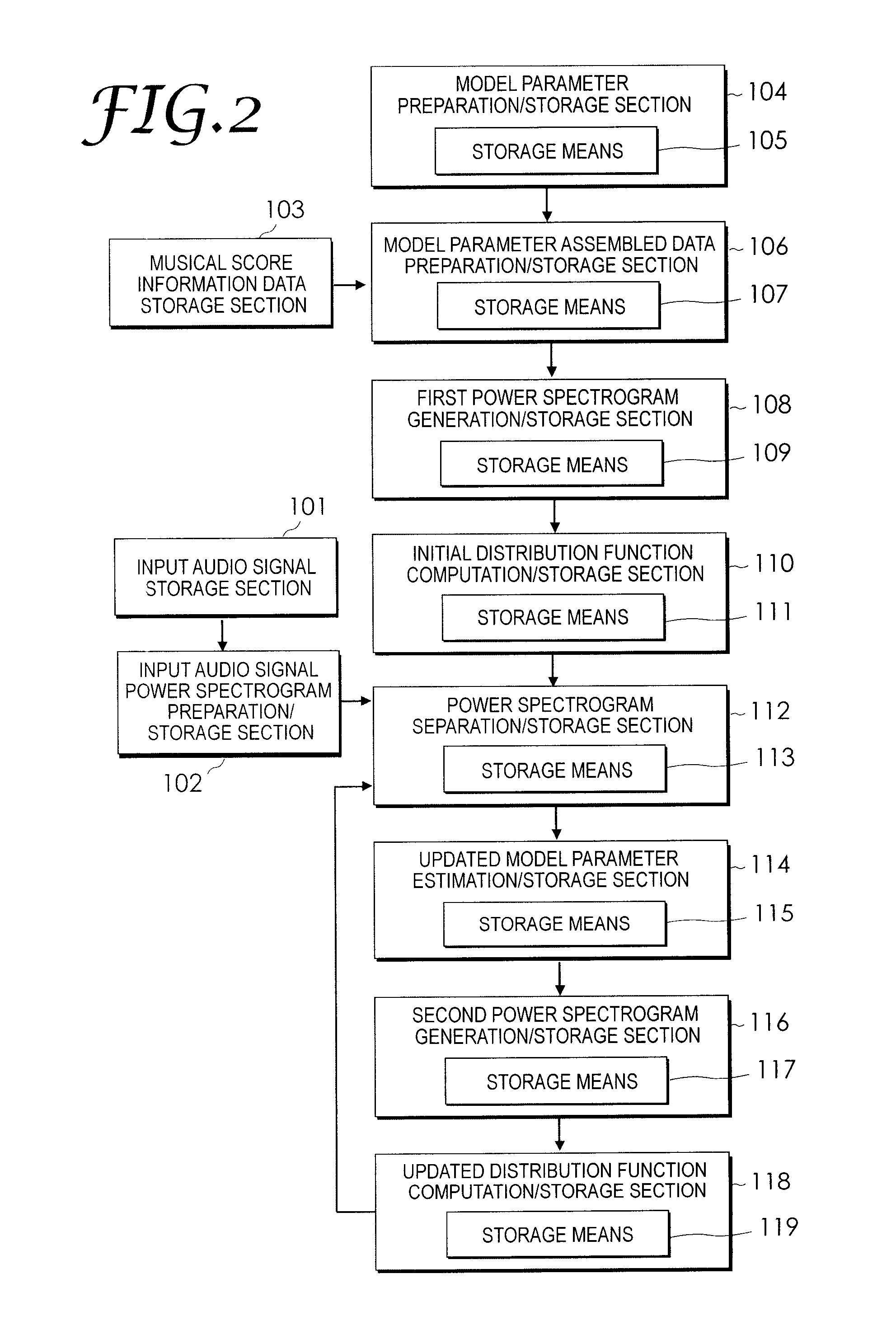
[0053]The best mode for carrying out the present invention (hereinafter referred to as “embodiment”) will be described in detail below.

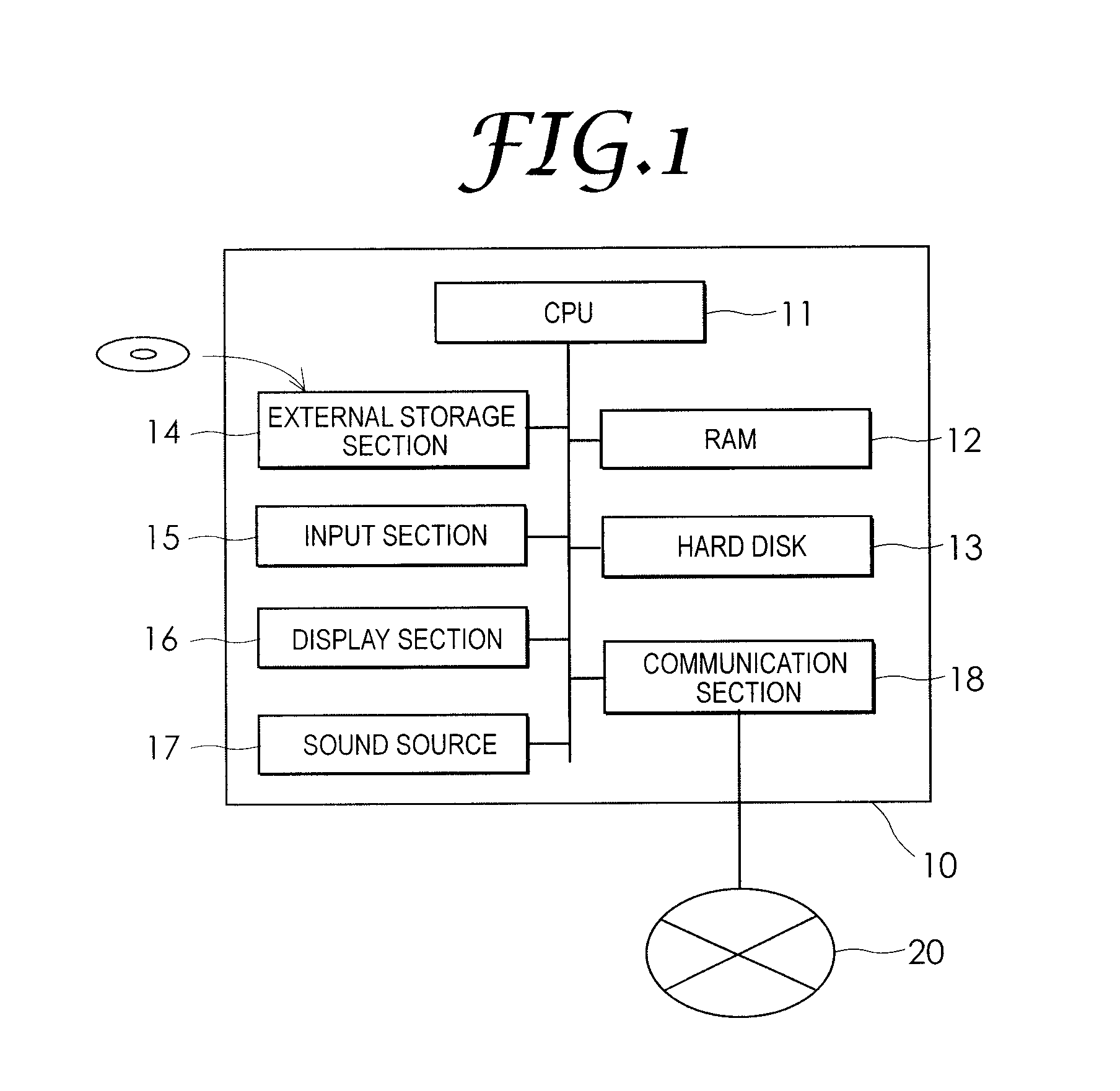
[0054]FIG. 1 is a block diagram showing an exemplary configuration of a sound source separation system according to an embodiment of the present invention implemented using a computer 10. The computer 10 includes a CPU (Central Processing Unit) 11, a RAM (Random Access Memory) 12 such as a DRAM, a hard disk drive (hereinafter referred to as “hard disk”) or other mass storage means 13, an external storage section 14 such as a flexible disk drive or a CD-ROM drive, a communication section 18 that communicates with a communication network 20 such as a LAN (Local Area Network) or the Internet. The computer 10 additionally includes an input section 15 such as a keyboard or a mouse, and a display section 16 such as a liquid crystal display. The computer 10 further includes a sound source 17 such as a MIDI sound source.

[0055]The CPU 11 operates as calculati...


PUM


Abstract

An audio signal produced by playing a plurality of musical instruments is separated into sound sources according to respective instrument sounds. Each time a separation process is performed, the updated model parameter estimation/storage section 114 estimates parameters respectively contained in updated model parameters such that updated power spectrograms gradually change from a state close to initial power spectrograms to a state close to a plurality of power spectrograms most recently stored in a power spectrogram separation/storage section. Respective sections including the power spectrogram separation/storage section 112 and an updated distribution function computation/storage section 118 repeatedly perform process operations until the updated power spectrograms change from the state close to the initial power spectrograms to the state close to the plurality of power spectrograms most recently stored in the power spectrogram separation/storage section 112. The final updated power spectrograms are close to the power spectrograms of single tones of one musical instrument contained in the input audio signal formed to contain harmonic and inharmonic models.

Description

TECHNICAL FIELD[0001]The present invention relates to a system, a method, and a program for sound source separation that enable separation of an instrument sound signal corresponding to each musical instrument from an input audio signal containing a plurality of types of instrument sound signals. The present invention relates in particular to a system, a method, and a computer program for sound source separation that separate an “audio signal of sound mixtures obtained by playing a plurality of musical instruments” containing both harmonic-structure and inharmonic-structure signal components into sound sources for respective instrument parts.BACKGROUND ART[0002]There is known an audio signal processing system that can separate an inharmonic-structure signal component such as from drums, for example, contained in a musical audio signal (hereinafter simply referred to as “audio signal”) output from a speaker to independently increase and reduce the volume of a sound produced on the ba...

Claims


Application Information

Patent Timeline
IPC IPC(8): G06F17/10G09B15/02G06F17/00G06G7/62G10L21/028G10L21/0308
CPCG10H1/0008G10H3/125G10H2210/066G10H2210/056G10H2210/301G10H2240/056G10H2250/031G10H2210/086
Inventor ITOYAMA, KATSUTOSHIOKUNO, HIROSHIGOTO, MASATAKA
Owner NAT INST OF ADVANCED IND SCI & TECH
Why Eureka
Try Eureka