
Method and system for real time interactive dynamic alignment of prosthetics

a dynamic alignment and prosthetic technology, applied in electrotherapy, diagnostics, applications, etc., can solve the problems of inability to achieve optimal alignment, inability to adapt to other user groups, and state of the art lack of known dynamic alignment systems or methods, etc., to achieve optimal dynamic alignment, optimal functional performance, and adaptability to other user groups

Active Publication Date: 2010-05-27
MOTEK
View PDF37 Cites 54 Cited by
  • Summary
  • Abstract
  • Description
  • Claims
  • Application Information

AI Technical Summary

Benefits of technology

"The present invention is a new technique and technology for real-time alignment of prosthetic limbs to their wearer. It involves a method for dynamic alignment of a prosthetic limb by a custom system and user interface that allows real-time blending of a motion database with data from a motion capture system. The system uses a combination of hardware and software elements to visualize and analyze the alignment errors and suggest corrections in real-time. The invention also includes a measurement and visualization tool for analyzing human motions in a real-time online or web environment. It provides a quantitative and objective way to compare and correct alignment errors in real-time, making the process more efficient and effective. The invention also includes a system of onboard actuators and sensors to enable computer or operator controlled adjustments to correct alignment errors while the subject is in motion. Overall, the invention improves the accuracy and efficiency of prosthetic limb alignment and provides a better understanding of the offsets and deviations from optimal alignment."

Problems solved by technology

There is currently no known objective way to get optimal alignment, as it is substantially based on subjective experience of the prosthetist.
At the present time, the state of the art does not seem to have a known system or method available for dynamically aligning accurately and objectively prosthetics such as prosthetic legs.
Modern prosthetic technologies are more complex but offer a greater span of dynamic function to the user when aligned properly.
One is the actual metabolic costs which is the peak exercise oxygen consumption [VO2] in mL / kg / m) of the person who has undergone amputation compared to that of intact people.
Increased metabolic cost for persons who have undergone amputations means the gait is inefficient compared to that of healthy intact persons, who require less endurance for any given distance.
A pathologic gait is inefficient and usually requires considerably more energy than a normal gait.
Stance-phase problems can occur in the gait of individuals with a TT prosthetic.
Inappropriate knee flexion can occur in the early stance phase, causing knee instability.
Several problems could arise from this flexion, including excessive ankle dorsiflexion, socket flexion, and posterior foot placement.
This is usually derived from inadequate side-to-side placement of the foot, excessive angulation of the socket, or wide mediolateral proximal socket dimensions that cause decreased knee control.
If an individual who has undergone a TT amputation is noted to have a foot slap in his or her gait, it may be a result of excessive socket flexion or foot dorsiflexion, the uneven placement of the foot, or a deficient heel height for proper prosthetic alignment.
Excessive forward progression of the tibia, or a drop-off gait can be caused by impaired rollover, shortening of the contralateral step length and swing time, and delayed heel-off.
If external rotation occurs in late stance, it can be caused by inadequate excessive anterior placement of the foot, excessive foot plantarflexion, or excessive hardness of the forefoot.
Early heel rise could result from inadequate placement of the foot (posterior), flexion contracture in the hip or the knee that was not accounted for in fitting the prosthetic, or excessive softness of the forefoot.
When prosthetic limb clearance is poor, the gait becomes pathologic.
Most predicaments occur because of poor suspension, a prosthesis that is too long, insufficient prosthetic knee flexion, or inadequate transfer of power from the residual limb to the prosthesis that decreases or delays knee flexion.
Foot drag is one of the most common problems of swing phase.
It is usually caused by inadequate suspension of the prosthesis, a prosthesis that is too long, or lower-limb weakness in the hip abductors or ankle plantarflexors on the contralateral side.
Any abnormal limb rotation is observed during the gait trial is usually caused by insufficient suspension of the prosthesis, misplacement of the suspension cuff-retention points, or overshooting of the hip or knee flexors to evade foot drop.
Limited knee extension or flexion problems can always be traced back to mechanical contractures, problems with the suspension, or problems with the knee joint in relation to a thigh corset.
As alluded to previously, knee flexion in the stance phase is one of the most common problems related to gait instability with TF amputations.
If a patient with a TF amputation is concerned about putting weight on the prosthetic leg because the knee flexion moment creates instability, an inefficient gait pattern results.
Prolonged knee extension in the stance phase is another problem that can occur with TF amputations.
This extension can result in shortening of the contralateral step and an increase in the vertical displacement of the center of gravity.
Occasionally, a person who has undergone a TF amputation can have an awkward downward movement of the upper body over the prosthesis, especially during fast walking.
In people who have undergone TF amputations, gait abnormalities in swing phase are limited in number.
Stiff-knee gait patterns can be the consequence of excessive knee stability in the joint that makes the creation of a flexion moment at the knee difficult.
Abnormal axis rotation at the knee that results in a whipping motion is usually due to incorrect alignment of the prosthesis at the knee.

Method used


Image

  • Method and system for real time interactive dynamic alignment of prosthetics
  • Method and system for real time interactive dynamic alignment of prosthetics
  • Method and system for real time interactive dynamic alignment of prosthetics

Examples


Embodiment Construction

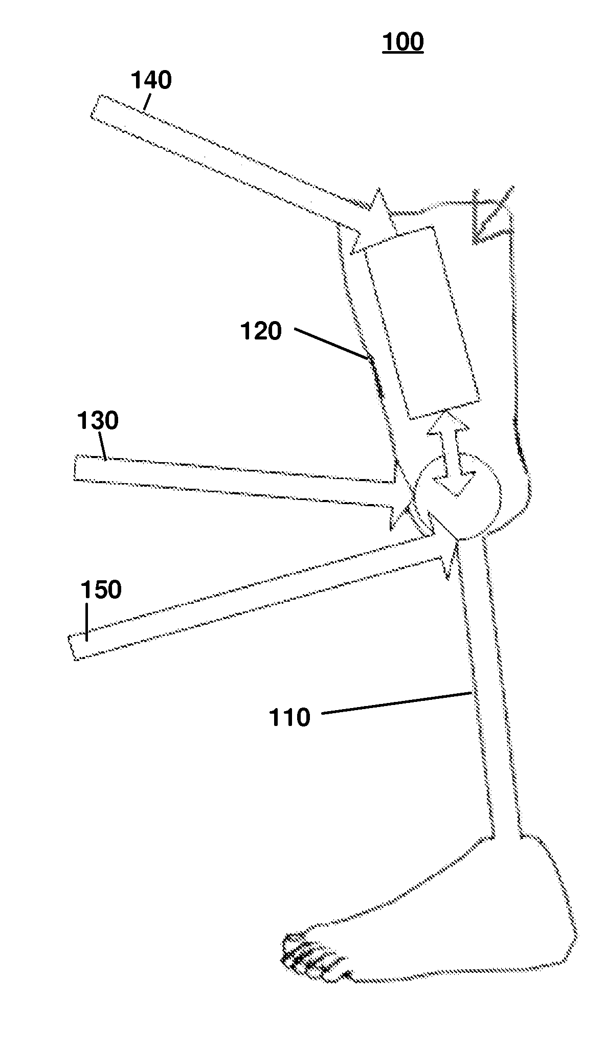
[0074]After the static alignment process of a prosthetic, a dynamic alignment is required. The dynamic alignment of a prosthetic limb is typically a visual estimative process that is subject to the skill and experience of the specialist doing the alignment. Such visual observation typically requires viewing the patient commence activity with the prosthetic attached and noting movement and querying the patient about discomfort.

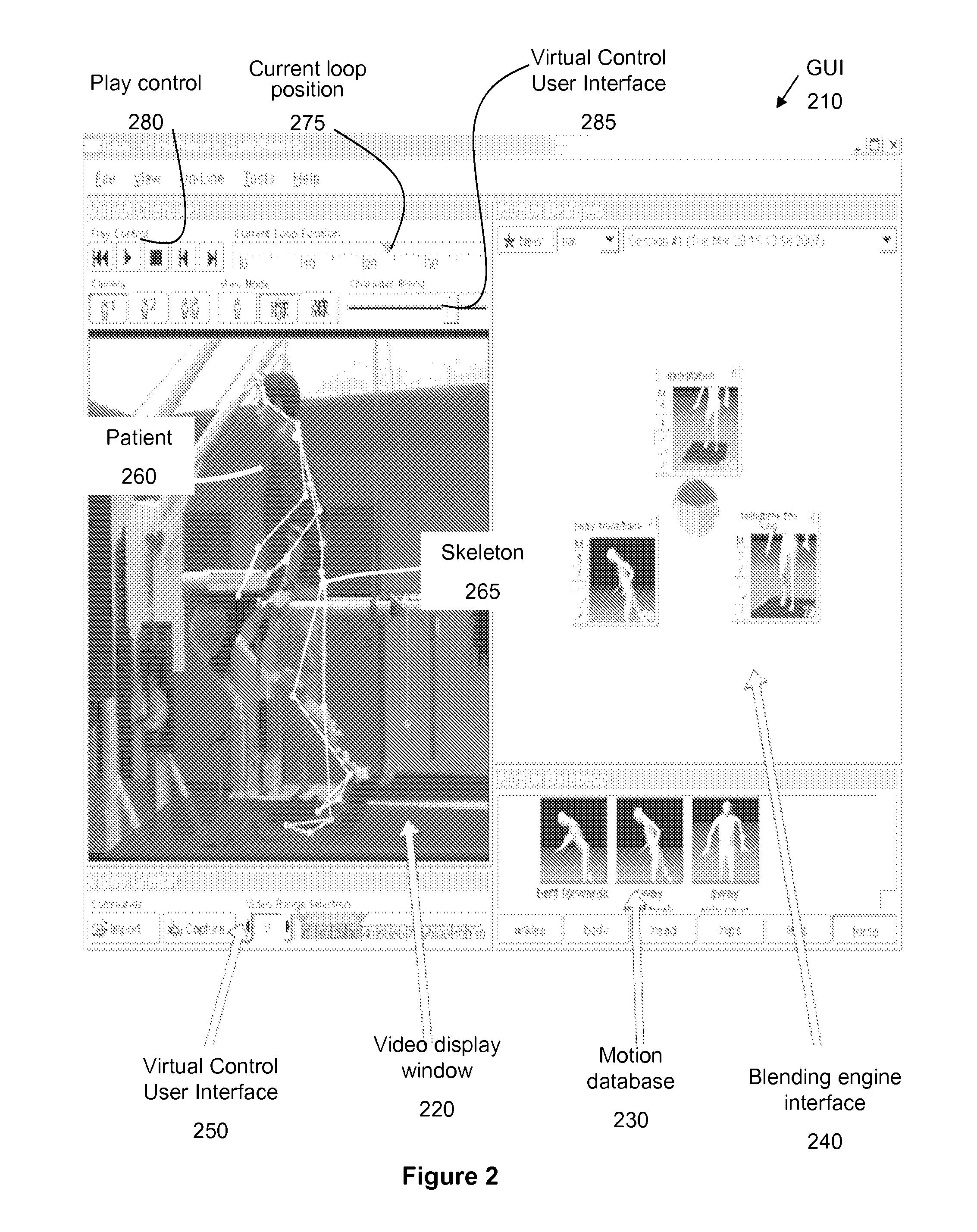
[0075]Various embodiments of the present invention provide tools that are useful in numerous applications, including the diagnostic and rehabilitation industries. This system allows or provides for the visualization of possible errors present in the prosthetic alignment for any given movement in real-time.

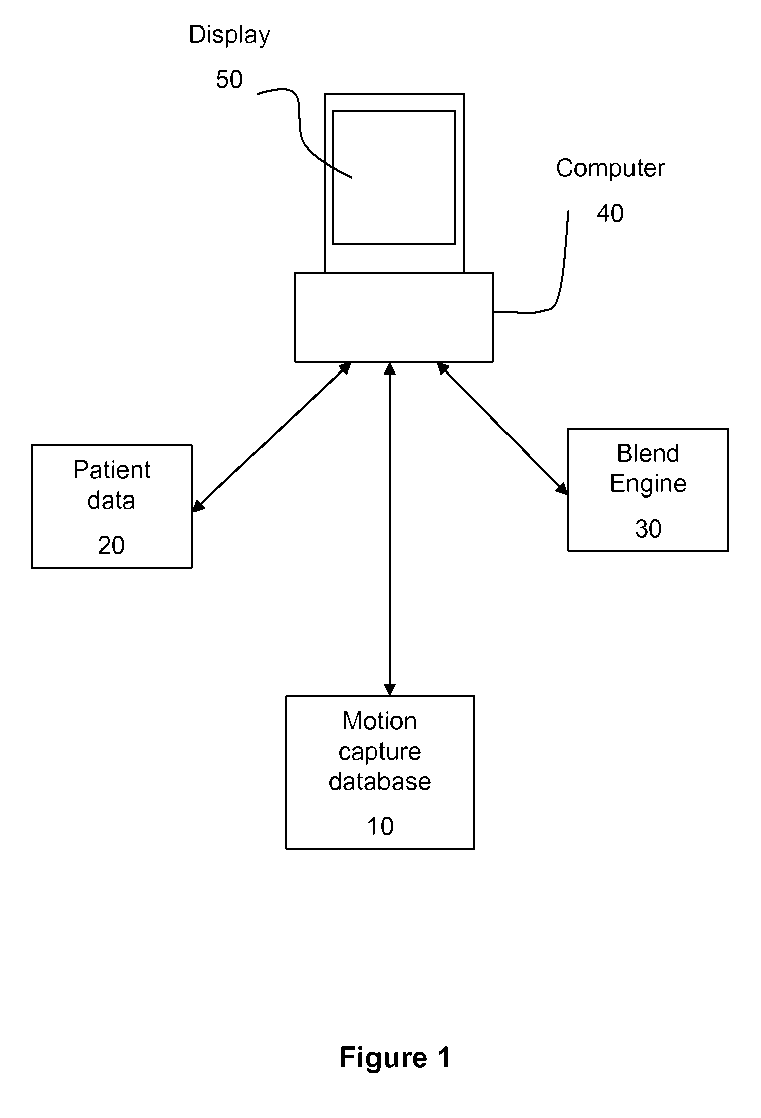
[0076]Motion blending is a term for a variety of techniques. Many motion editing algorithms, including transitioning and multi target interpolation, can be represented as instances of a more general operation called motion blending. Some use data structures ca...


PUM


Abstract

An objective method and system for dynamic analysis of prosthesis-bound subjects for determining optimal prosthesis alignment adjustments consists of a motion detection system, motion database, blending engine and algorithms, and a graphical user interface with suitable program controls whereby manual, semi-automatic, or fully automated analysis of a prosthesis-equipped subject's motion performance can be done in real time to determine objectively the optimal adjustments for the subject's prosthesis in a precise clinical protocol context.

Description

RELATED APPLICATIONS[0001]This application claims the benefit of U.S. Provisional Application No. 60 / 915,780, filed 3 May 2007, and is herein incorporated in its entirety by reference.FIELD OF THE INVENTION[0002]This invention most generally relates to a method and system for facilitating prosthetic adjustments. Motion sensors combined with motion blending algorithms and a three dimensional (3D) computational software engine create a real time environment where dynamic alignment of prosthetic limbs can be done in an objective and exact clinical protocol context.BACKGROUND OF THE INVENTION[0003]There are many tragic injuries and illnesses in the world, and one of the most vivid reminders of these is amputees. It is estimated that there are 70,000 major amputations performed annually in the United States alone, and more than 200 million amputations each year in the world. Many of these are major limb amputations of the lower extremities.[0004]In an effort to improve the life of the am...

Claims


Application Information

Patent Timeline
Patent Type & Authority Applications(United States)
IPC IPC(8): G01M1/38G06F3/048
CPCA61B19/50A61B19/52A61B19/56A61B2019/461A61F2002/7695A61F2/68A61F2/76A61F2002/705A61F2/60A61B90/36A61B34/25A61B2090/061A61B34/10A61F2/70
Inventor EVEN-ZOHAR, OSHRI
Owner MOTEK
Learn More