Start-Up Control For a Compact Lightweight Turbine

a turboengine and lightweight technology, applied in the direction of turbine/propulsion fuel control, engine lubrication, air transportation, etc., can solve the problems of high maintenance cost, high complexity, and heavy engine weight per unit of delivered power, and achieve the effect of simple and inexpensive yet reliabl

Inactive Publication Date: 2010-06-03
MANDOLIN FINANCIAL PROPERTIES NO 613345
View PDF14 Cites 37 Cited by
  • Summary
  • Abstract
  • Description
  • Claims
  • Application Information

AI Technical Summary

Benefits of technology

[0023]An object of the invention is to provide a simple and inexpensive yet reliable method and means for controlling the start-up sequence in a turbo-engine. A particular object is a turbine start-up control method and means which may be started simply by the turn of a key for similar action) to proceed immediately thereafter until the turbine has gathered enough speed for turning the fuel injectors on. According to the invention, the fuel injectors are triggered automatically by a simple relay trip signal which is triggered by sensing the oil pressure when the turbine has reached the right speed. The start-up sequence continues a short time more and is terminated when the turbine has gathered enough speed to operate in a permanent self-sustainable mode.

Problems solved by technology

Reciprocating engines use up a lot of closed space which has to be adapted to tolerate heavy weights and medium- and low-frequency vibrations, high maintenance costs and a narrow range of fuels.
Furthermore, these engines take a long time to warm up and get into condition for connecting to the power lines, which hinders their availability to swiftly respond to demand or else causes high maintenance costs when it is stopped for servicing to be carried out while still hot to reduce the outage time.
Compared to turbo-engines, these engines are heavier per unit of delivered power, highly complex because of the large quantity of moving parts they contain and require periodic specialized inspections.
Light one-to-four seating helicopters are particularly penalized because there is no alternative for them other than combustion engines.
Therefore, their capabilities are severely restricted by the need to carry a heavy power plant, a significant weight compared to one or more passengers.
Stresses and vibrations transmitted to the whole helicopter and to the passengers or the use of reciprocating engines further significant deter use of these helicopters.
On the other hand, an unfavorable feature is that turbo-engines lack massive oscillating or eccentric mechanisms, hence dynamic high-amplitude and low-frequency stresses are transmitted to the structure thereof.
Combustion engines may only use aircraft petrol which is very volatile and explosive, leading therefore to safety concerns.
Too early fuel injection of fuel would lead to an excessive rise of temperature inside the combustion chamber (because the turbine speed is below the predetermined point and there is not enough air intake to match the fuel flow) and, depending on how early fuel injection began, would produce a dangerous flame out from the exhaust duct of the turbo-engine or there would be no ignition at all leading to an undesirable accumulation of unspent fuel in the combustion chamber.
One of the greater technical problems in designing an efficient, low-power turbine is that, due to physical operational principles, a reduction in the flow capacity and size thereof leads to having to increase the rotation speed of the compressor-turbine assembly, thereby significantly increasing mechanical stress on the moving parts materials.
This conditions the life-term of the components and is in part associated with the wear of the moving parts.
The electronic components for signal processing and amplification are subjected to electro-magnetic noise and electrical failures, so that relying on such electronic means raises reliability concerns and, even more serious, is potentially physically hazardous for the human operator.
Hence a drawback is the need for an additional coupling gear, resulting in more parts, weight and difficult disassembling, detrimental to compactness and simplicity.
These devices have to be adjusted with extreme precision because of the narrow tolerances they are built around and are intensely affected by variations of atmospheric conditions.
Since these mechanisms are made up of a number of parts, it is considerably expensive and difficult to include redundant systems to improve the reliability thereof and of the entire engine turbine in general.
Furthermore, the operation of these mechanisms involves a complex ignition and control procedure during which the different ignition stages have to be manually enabled and disabled, opening the door to a new range of potential faults arising from human operational errors.
Although this reduces the probability of human error, yet more systems are added to the already extremely complex systems of the turbine per se, adding further penalties in terms of cost and weight and introducing new fault sequences.
Because the auxiliary systems of the turbo-engines are complex, the power consumed by the auxiliary systems of high-power turbo-engines is similar to that of the systems of small turbo-engines.
This curtails the design and implementation of low-power turbo-engines, as upper limits in the power consumption of auxiliary systems come into play in order for the operation of the turbine at low-power cruising speeds be self-sustainable.
This prior art has the drawback that the control valve has to be operated via servomechanisms or else by means of the usual control cables, adding more devices with their attendant fault and maintenance rates.
In general, it can be said that the traditional aircraft turboshaft designs cannot be extrapolated down to the low-power range and still match the reliability, durability, efficiency and simplicity required in commercial aviation or avoid drawbacks in maintenance and wear for the generation of electricity or useful work on the ground.
As explained hereinbefore, this is due to the complexity and technical problems that need to be overcome go up as the power and the size thereof go down.
Proof of this is that available low-power turboshafts used for fixed or military installations are very complex, have limited lifespan, require a lot of maintenance and are pretty expensive considering the low power levels involved.

Method used


Image

  • Start-Up Control For a Compact Lightweight Turbine
  • Start-Up Control For a Compact Lightweight Turbine
  • Start-Up Control For a Compact Lightweight Turbine

Examples


Embodiment Construction

The Combustion Chamber System:

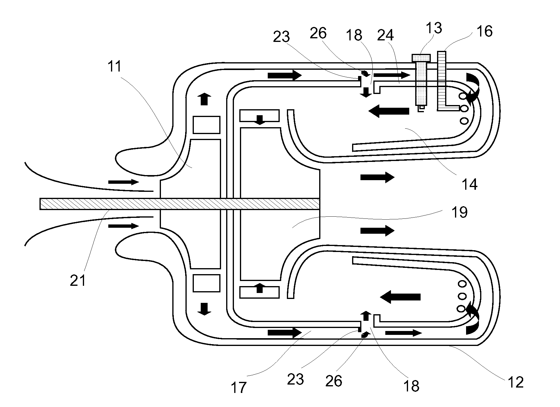
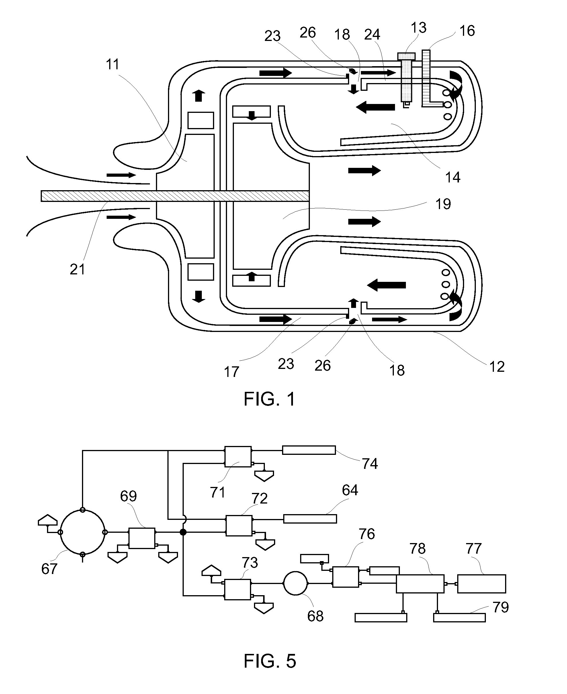
[0032]FIG. 1 illustrates a compact turbo-engine which may be used for the present invention, designed for use in light airplanes and helicopters. The compact turbo-engine includes an air-compression stage 11 comprising a 200-HP centrifugal compressor 11 of the radial-vane type, and an annular combustion chamber 12 including a cold peripheral region 17, a hot central region 14 and a fuel counter-flow injection system comprising redundant electrically-operated nozzles 16 for injecting fuel into the combustion chamber 12 against the gas (air) flow direction. Sparking plugs 13 are located in the hot region 14 for igniting the fuel and gas mixture during start-up.

[0033]The combustion chamber 12 is of a compact, toroidal shape so that the distance travelled by the air inside the chamber is longer than the major axis of the chamber 12. The combustion chamber 12 is made of Inconel 713 material, measures about 150 mm long by 260 mm external diameter and is provi...


PUM


Abstract

In a turbo-engine system, oil is circulated by means of a positive-displacement pump directly driven by the output shaft. The pump output pressure is monitored to trigger fuel injection when the turbine reaches sufficient speed during the start-up sequence.

Description

CROSS-REFERENCE TO RELATED APPLICATIONS[0001]The present application is a continuation-in-part of my U.S. patent application entitled “Compact Lightweight Turbine,” Ser. No. 11 / 404,265 filed on Apr. 13, 2006 as a continuation-in-part of my U.S. patent application Ser. No. 10 / 827,943 filed Apr. 20, 2004 and now U.S. Pat. No. 7,065,954 entitled “Compact Lightweight Turbine” and which issued on Jun. 27, 2006, the disclosures of which are all hereby incorporated herein by reference.FIELD OF THE INVENTION[0002]The present invention is related to a compact, lightweight, efficient and durable turbo-engine able to deliver power to a shaft as well as thrust from the reaction of the exhaust gases and heat. One practical application of the present turbo-engine is for generating electricity. Another application is for propeller-driven aircrafts whether airplanes or helicopters, in marine uses for driving an under-water propeller, or any other application requiring delivery of power to a rotary ...

Claims


Application Information

Patent Timeline
Patent Type & Authority Applications(United States)
IPC IPC(8): F02C9/26F02C7/26
CPCF01D25/18Y02T50/671F02C7/26F02C7/06Y02T50/60
Inventor LABALA, GUSTAVO FRANCISCO
Owner MANDOLIN FINANCIAL PROPERTIES NO 613345
Why Eureka
Try Eureka