
Ferrule for making fingertight column connections in gas chromatography

a technology of ferrule and gas chromatography, which is applied in the direction of pipe supports, components, pipe elements, etc., can solve the problems of destroying affecting the integrity of chromatographic separation, and unsuitable metal connection systems, etc., and achieves advantageously diminishing the radial thickness

Active Publication Date: 2010-06-03
TRAJAN SCI AUSTRALIA
View PDF24 Cites 17 Cited by
  • Summary
  • Abstract
  • Description
  • Claims
  • Application Information

AI Technical Summary

Benefits of technology

The invention provides a ferrule arrangement for sealing connections to gas chromatography columns. The ferrule has a tapered tip region that can be deformed into sealing engagement with the column's protective coating without breaking it. The ferrule and a former can be moved relative to each other using finger force, and the arrangement includes a connector component that can be rotated using finger force to join the ferrule and former together. The ferrule has an intermediate part with larger outer diameter and a forward part with smaller outer diameter that tapers to a point. The tip region of the ferrule is thin enough to allow for finger force application. The invention also provides a ferrule for use in sealing connections to gas chromatography columns.

Problems solved by technology

Glass columns were introduced in the 1960s and immediately the all metal connection systems were unsuitable since they promptly broke the column.
Graphite ferrules were permeable to oxygen, which causes problems with detectors and damage to capillary columns.
The ferrule should not normally come in contact with sample components but it is recognised as a problem that pieces of graphite can become detached or extrude into parts of the chromatographic system thus destroying the integrity of the chromatographic separation.
One of the main problems with polyimide and graphite-impregnated polyimide ferrules was that after an initial leaktight seal was made and the chromatographic system was heated, as is required in chromatographic analysis, and then the system cooled down in preparation for the next analysis, the polyimide ferrule developed substantial leaks necessitating the retightening of the fitting to re-establish the leaktight seal.
This put the ferrule under significant compression at high temperatures causing it to creep dimensionally.
As the fitting system was cooled, the polyimide ferrule contracted more than the metal fitting encapsulating it, which caused gaps and leakage paths to be formed.
Any damage from scratches (even from dust particles) or chemically from moisture in the environment causes the material to be highly brittle and structurally unstable so that it easily fractures.
For many years, these various' deficiencies of existing graphite and polyimide ferrule systems diminished the reliability of chromatography systems, leading to compromised performance as well as non-productive time in rectifying the faults.
In addition, damage to components in the systems regularly occurred when operators applied excessive force to fittings in efforts to eliminate leaks.
The structure disclosed in WO 01 / 73338, and the actual product brought to market by the assignee, did continue to share one disadvantage with the predecessor arrangements that relied on graphite or polyimide ferrules: in gas chromatography, a tool such as a wrench or spanner lever was necessary to reliably deliver the necessary compression force.
In contrast, fitting systems used in liquid chromatography (LC) can be tightened with just the application of finger force but these have very different requirements in terms of the level of leak tightness and high temperature needs, and they are not sealing directly onto thin wall fracturable glass.
There have been a number of attempts over the last 20 years to commercialise simplified GC connector systems that did not require spanners but none have been successful.

Method used


Image

  • Ferrule for making fingertight column connections in gas chromatography
  • Ferrule for making fingertight column connections in gas chromatography
  • Ferrule for making fingertight column connections in gas chromatography

Examples


Embodiment Construction

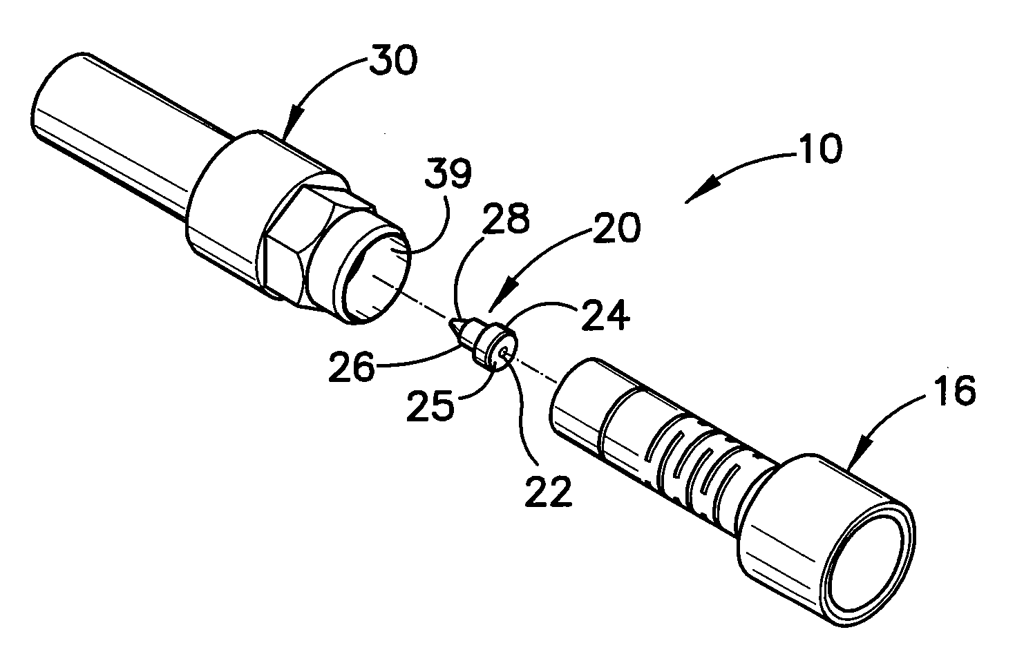
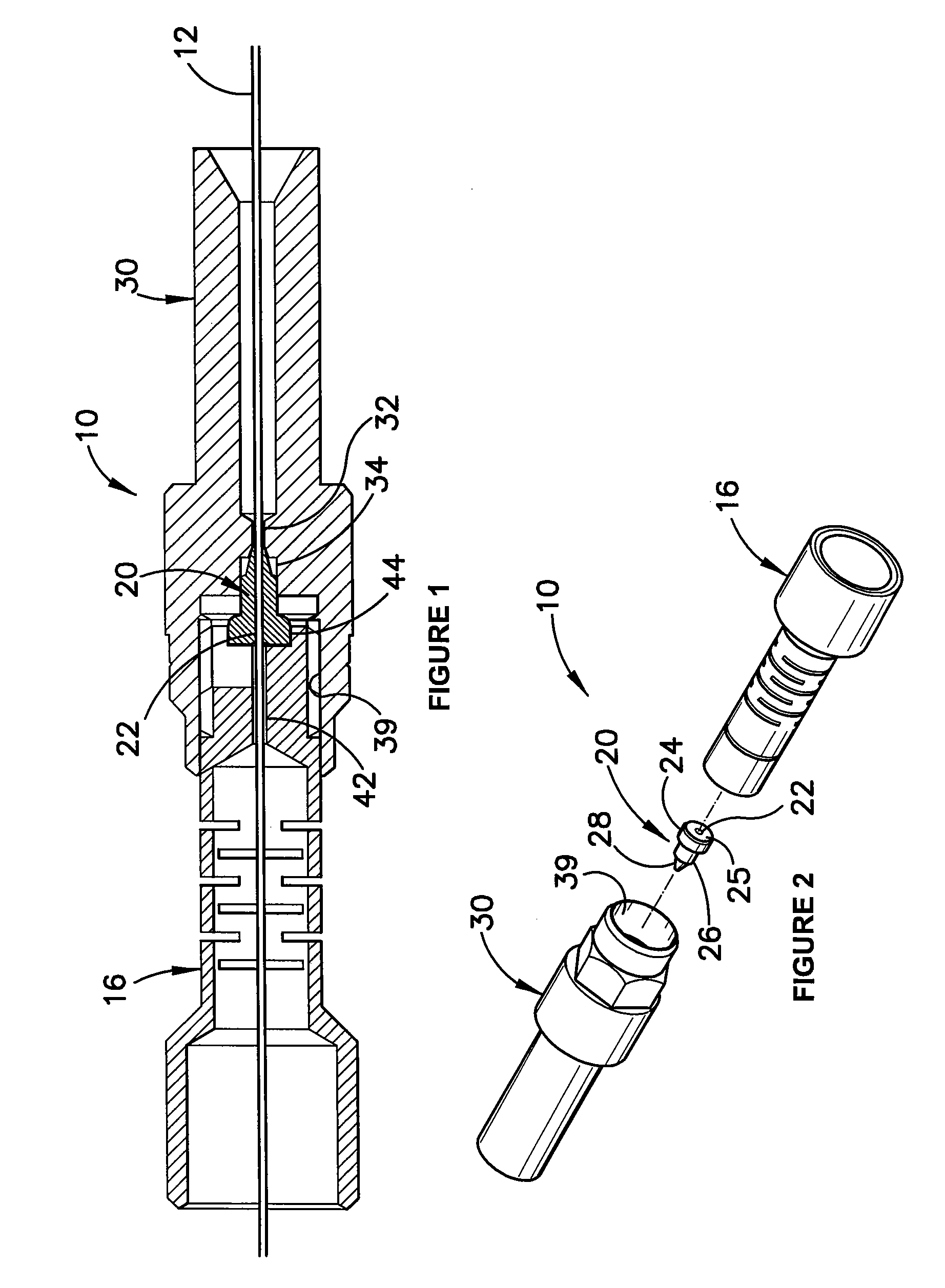
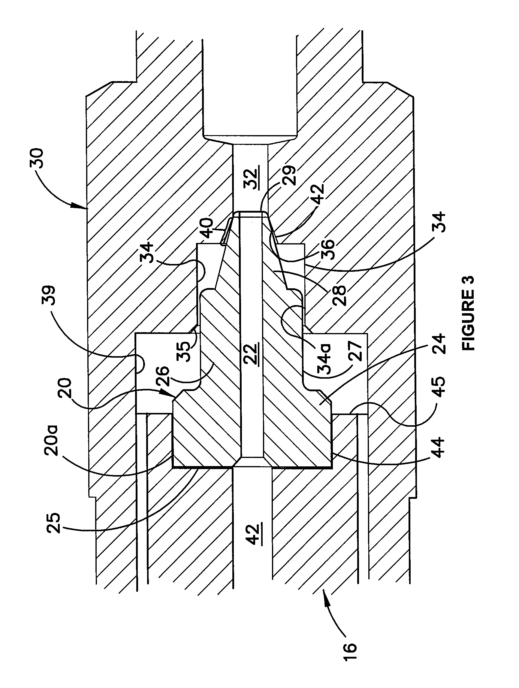
[0030]FIG. 1 illustrated a typical connection assembly 10 at an inlet end of a fused silica column 12. The assembly includes a generally tubular female column connector 30, a complementary male column connector 16, and, centrally seated in respective co-axial counterbores 34, 44, a ferrule 20. Male and female connectors 16, 30 are threadingly engaged at internal interface 39 for relative axial movement by relative finger rotation of the two components.

[0031]Ferrule column connector 30 serves as former for ferrule 20. All three components are preferably formed in stainless steel and all have a central bore 22, 32, 42 to receive a fused silica glass tube 12, which is of the kind commonly employed as a column in gas chromatography. This tube 12 may generally be of outside diameter 0.3 to 1.0 mm and typically has a protective polyimide coating of thickness around 15 micron, although it may be in the range 5 to 100 micron. Other coatings are also known, including silicone and, for specia...


PUM


Abstract

A ferrule arrangement for use in sealing connections to gas chromatography columns includes a generally tubular metal ferrule with an axial bore to receive a fracturable column with a protective coating. The ferrule has a forward part that tapers to a tip region of the ferrule. A generally tubular former has a socket portion to receive the ferrule and further has an internal conical surface that, after such receipt, engages the forward part of the ferrule. A portion is provided on either or both of said ferrule and the former by which the ferrule and former may be directly or indirectly relatively moved together by application of finger force. The taper and the internal conical surface exhibit relative taper angles and the tip region of the ferrule is sufficiently radially thin whereby the application of finger force (i) is adequate to move the ferrule axially into the former to cause the conical surface to engage the tip region of the ferrule and to deform the tip region into sealing engagement with the protective coating of the column, but (ii) does not break the column.

Description

FIELD OF THE INVENTION[0001]This invention relates generally to the sealing of fittings about fracturable tubes and as such is of particular, though not exclusive, interest in the sealing of connections to fused silica capillary columns in gas and liquid chromatography generally but more particularly in gas chromatography.BACKGROUND OF THE INVENTION[0002]In gas chromatography (GC) the sample to be analysed is introduced into the inlet end of a separation column and carried through the column by a carrier gas which is necessarily of high purity. To retain the sample to be analysed in the gas phase, it is usually necessary to heat the column to an elevated temperature. The inlet end of the column is usually above atmospheric pressure to allow the gas to be forced through the column. Consequently, the connection at the inlet end of the column needs to be gastight so as not to allow leakage from the column or introduce contamination into the column. The outlet end of the column can be c...

Claims


Application Information

Patent Timeline
Patent Type & Authority Applications(United States)
IPC IPC(8): F16L25/06
CPCF16L7/02F16L25/06G01N30/6039G01N30/6026F16L33/32
Inventor BARNETT, BRETT RUSSELLDAWES, PETER ALEXANDER
Owner TRAJAN SCI AUSTRALIA
Learn More