

Ground detection circuit for video signal driver to prevent large clamp transistor current
a video signal driver and clamp transistor technology, applied in the emergency protective arrangement of limiting excess voltage/current, television systems, electrostatic charges, etc., can solve the problem of additional hardware cost being spent on grounding unused video signal lines
- Summary
- Abstract
- Description
- Claims
- Application Information
AI Technical Summary
Benefits of technology
Problems solved by technology
Method used
Image

Examples
first embodiment
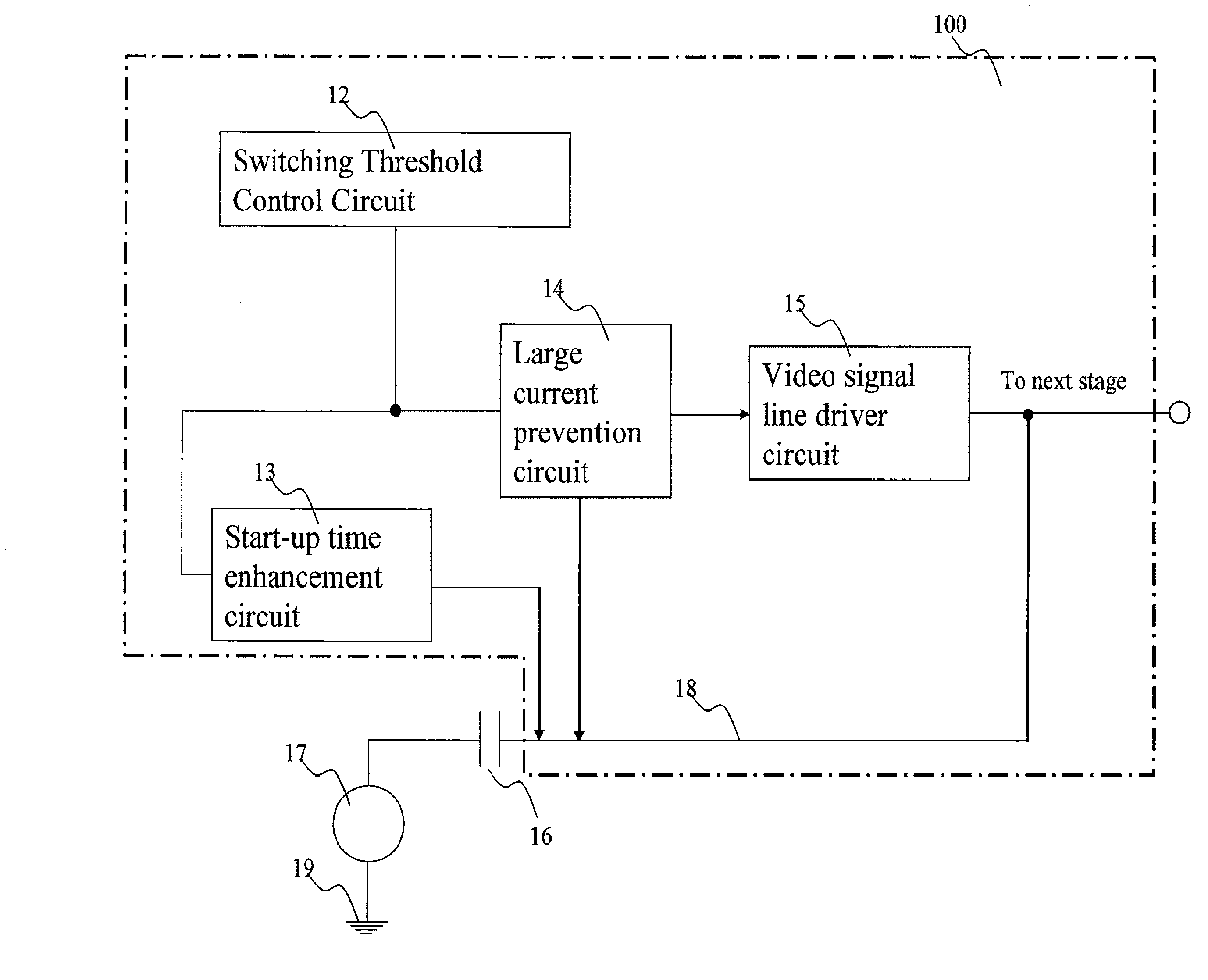
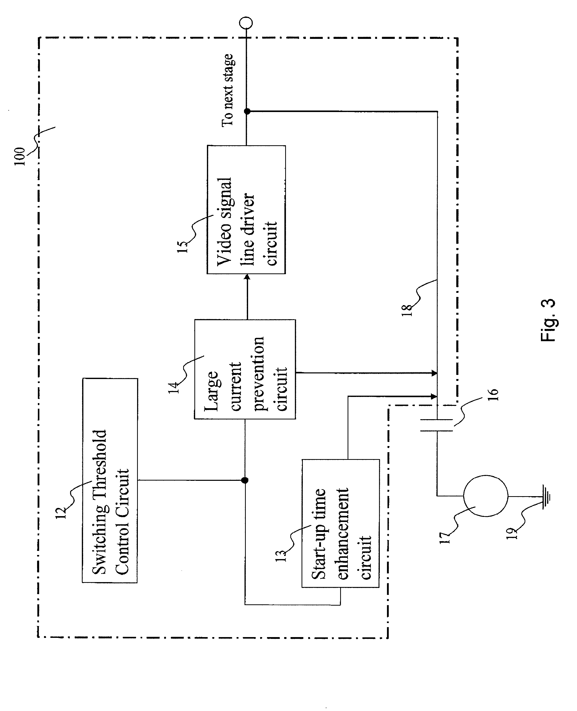
[0029]Referring to FIG. 3, a first embodiment of a system configuration of ground detection circuit for video signal line driver according to the present invention is shown.
[0030]The ground detection circuit 100 for video signal driver has a switching threshold control circuit 12, start-up time enhancement circuit 13, large current prevention circuit 14 and video signal line driver circuit 15.
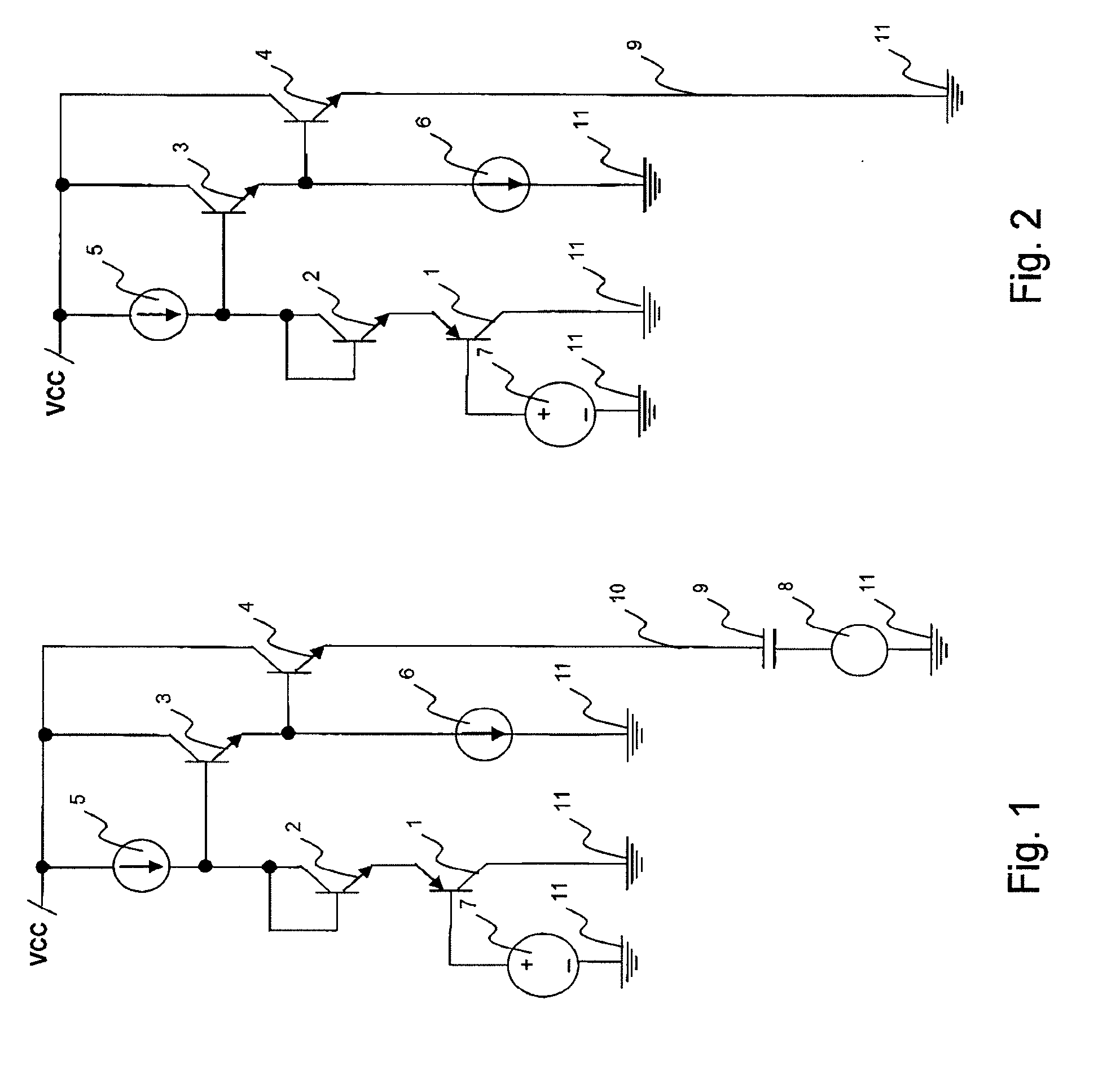
[0031]Video source 17 is connected to video signal line 18 through AC coupling capacitor 16. Video signal line driver circuit 15 is a circuit used for transmitting video signal along video signal line and setting a pre-determined DC level for video source 17 to ride on. In conventional design shown in FIG. 2, if video signal line 9 is being shorted to ground terminal 11, video signal line driver circuit 15 shown in FIG. 3 will source large current into the video signal line 18.
[0032]Referring to FIG. 3, the ground detection circuit 100 proposed in this invention has such system configuration, s...
second embodiment
[0038]Referring to FIG. 4, a second embodiment of ground detection circuit 100 for video signal line driver, demonstrating an exemplary implementation of the system as described in embodiment 1 is shown.
[0039]Referring to FIG. 4, the combination of transistors 19, 20, 21, 22 and current sources 23 and 24 form an example of an implementation of the video signal line driver circuit 15 as shown in FIG. 3. Current source 23 and transistors 19 and 20 form a level shifter circuit so that voltage level at the base of transistors 21 is 2Vbe above bias voltage 25. Transistor 21 and current source 24 provide sufficient base current for transistor 22. Transistor 22 is a large NPN to provide sufficient current drive to transmit video signal 26 along video signal line 39 at pre-determined DC level. The pre-determined DC level is (Bias voltage 25+Veb of Transistor 19+Vbe of transistor 20−Vbe of transistor 21−Vbe of transistor 22).
[0040]Referring to FIG. 4, the combination of transistors 26, 27, 2...
third embodiment
[0058]Referring to FIG. 5, a third embodiment of ground detection circuit 100 for video signal line driver, demonstrating another exemplary implementation of the system as described in embodiment 1 is shown.
[0059]The only difference between circuit shown in FIGS. 4 and 5 is that a band gap voltage source 41 is connected to base of transistor 26, as shown in FIG. 5. On the other hand, in FIG. 4, base of transistor 26 is connected to a pre-determined DC fixed by voltage divider, which is formed by resistors 29 and 30.
[0060]Referring to FIG. 5, and as previously described in embodiment 2, similarly, switching threshold control circuit 12 will set the voltage at the base of transistor 33 and 34 at a pre-determined value. This pre-determined level will control switching threshold of large current prevention circuit 14 and start-up time enhancement circuit 13.
[0061]The purpose of connecting band gap voltage source 41 to base of transistor 26 as shown circuit in FIG. 5 is to reduce tempera...
PUM
 Abstract
Description
Claims
Application Information