Method and device for measuring underground pressure

a pressure measurement and underground technology, applied in the field of inplace soil stabilization, can solve the problems of insufficient bearing capacity of the underlying soil for the intended structure's design, inconvenient use, and inconvenient maintenance of the new soil strength, so as to achieve the effect of reducing the confined soil strength, and ensuring the stability of the new soil

Inactive Publication Date: 2010-06-03
URETEK USA
View PDF6 Cites 15 Cited by
  • Summary
  • Abstract
  • Description
  • Claims
  • Application Information

AI Technical Summary

Benefits of technology

[0015]In one embodiment, the present invention provides ongoing differential pressure change data taken from selected soil zone(s) both during the injection process and after completion of the process. Through the injection and monitoring of various substances, such as but not limited to expanding polymers, confined soil strength specifications can be achieved and assured. The invention can work with a variety of injectable substances, including but not limited to polymers, hydraulic systems, grout, cement, concrete, and chemicals.
[0017]The system disclosed herein provides engineers with a simple method to monitor and to document improvements in soil strength. This capability accommodates any desired safety margin for soil strength necessary to support present and future dead load and live load requirements.
[0023]Presently, the preferred reaction time for expansion of the polymer from liquid state to the expanded condition is less than one minute (30 to 45 seconds), though other reaction times may be used. In one embodiment, the short expansion time permits control of the injection process by allowing the injection technician periodically (typically every 5-20 seconds) to add more polymer into the soil strata to achieve greater expansive force and higher confined soil strength. When the desired confined soil strength is reached, as indicated by the pressure sensor, further injection is stopped and the material will cure and harden in place thus maintaining the new soil strength.

Problems solved by technology

The bearing capacity of the underlying soil is not always sufficient for the intended structure's design and use.
Existing structures may also experience differential deflection or settlement due to unconsolidated soil strata, water infiltration, decomposition of organic materials, void conditions, poorly executed site preparation during original construction, additional live loads, soils consolidation from on-site vibration caused by equipment or traffic operations, et cetera.
Such construction systems are invasive, disruptive, time consuming, and often unsuitable for pavements, lightweight slab, and other applications.
This system did not address the need for soil remediation as indicated by measurement of increased confined soil strength at depth.
This system does not address the need to continuously measure and monitor, at depth, the amount of improved compaction of the targeted soil.
This system does not monitor unknown and unexpected migration of the injectable material away from the injection site creating unexpected surface lifting some distance away from the desired location.
Such measurement fails to monitor and measure the precise confined soil strength at depth.
However, this test fails to be useful in determining the confined soil strength at a particular depth, and fails to provide a way to document evidence of confined soil pressures gained from the injection process.
The previous systems fail to provide a system of monitoring and control in situ at depth and do not measure the differential, real-time increase in confined soil strength as the expanding polymer is introduced.
The previous systems do not provide a means to document the strength gained from the injection process.
Previous methods have not met the need of providing in situ real-time soil strength data at various soil depths.
Thus, previous methods also fail to indicate when geotechnical engineering specifications have been met or exceeded.

Method used


Image

  • Method and device for measuring underground pressure
  • Method and device for measuring underground pressure
  • Method and device for measuring underground pressure

Examples


Embodiment Construction

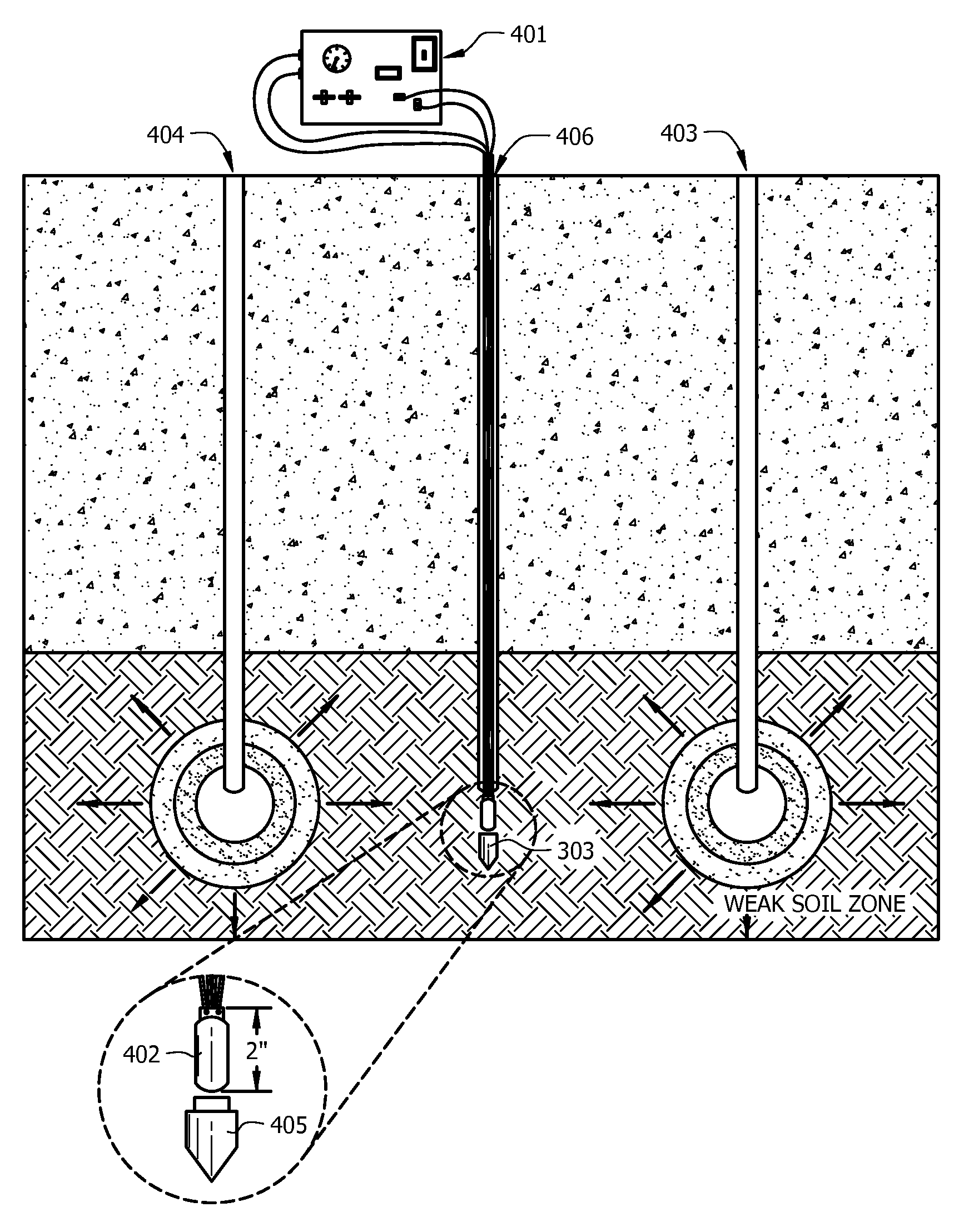
[0036]The present invention can be used with one injection site or multiple injection sites. As an example of multiple injection sites, see U.S. Pat. No. 6,634,831, which has already been incorporated by reference in its entirety.

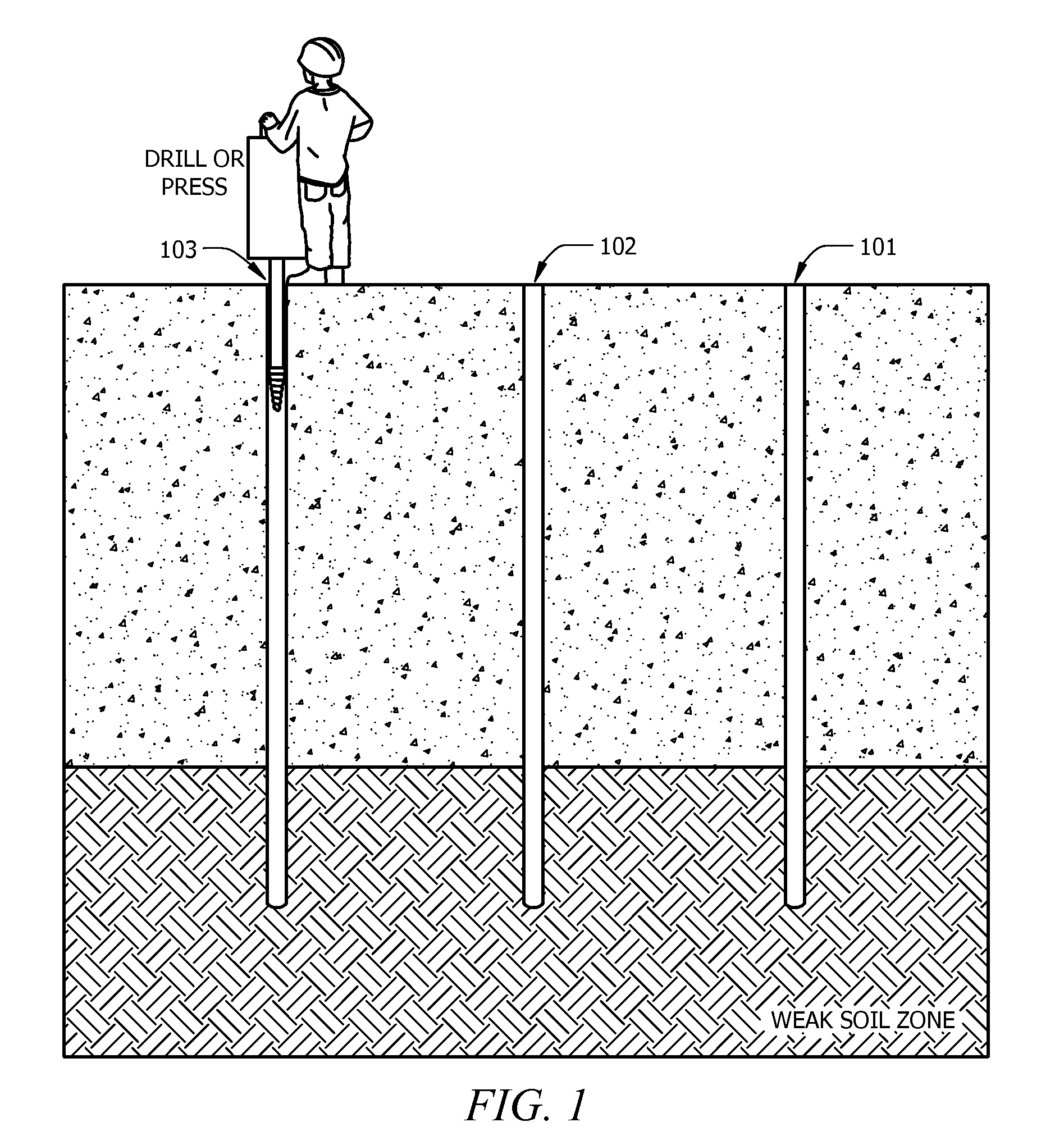
[0037]One or more holes are created by drilling, pressing, or vibration intrusion into compromised soil strata (less than desirable confined soil strength) subsurface locations. (See FIG. 1). As shown in FIG. 1, polymer injection holes, 101 and 103, and the sensor hole, 102, are drilled into the weak soil zone. In some embodiments, the holes are ⅝″ in diameter. In other embodiments, the holes are spaced three to six feet apart.

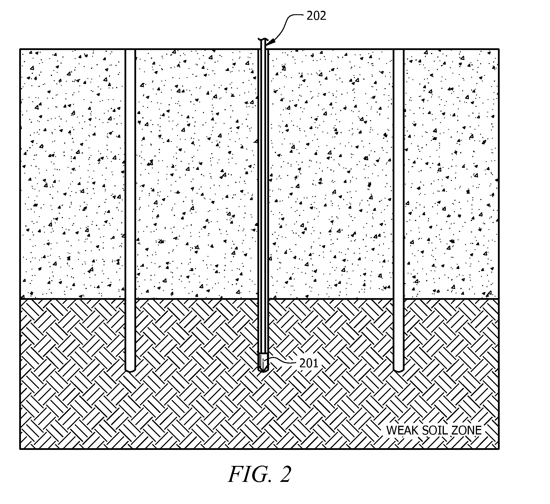
[0038]Optionally, a tube may be placed in the one or more holes. Optionally, the lower tip of the tube is closed over with any device suitable for keeping soil from entering the tube. Non-limiting examples of such a device are tape or a small conical insert tip (i.e., made of metal or hard plastic). FIG. 2 shows a conical tip, 201, in...


PUM


Abstract

The present invention relates to in-place soil stabilization. Specifically, the present invention relates a method and device for measuring the increase in subsurface earth pressure during the injection of a stabilizing agent into the soil. The rise in sensor pressure indicates an increase in soil strength and bearing capacity. Therefore, real-time monitoring of these pressures may serve as a guide during the injection process.

Description

CROSS-REFERENCE TO RELATED APPLICATIONS[0001]This application claims the benefit of U.S. Provisional Application Ser. No. 61 / 116,957, filed Nov. 21, 2008, the entire contents of which are hereby incorporated herein by reference.TECHNICAL FIELD[0002]The present invention relates to in-place soil stabilization. Specifically, the present invention relates a method and device for measuring the increase in subsurface earth pressure during the injection of a stabilizing agent into the soil. The rise in sensor pressure indicates an increase in soil strength and bearing capacity.BACKGROUND OF THE INVENTION[0003]The present invention relates a method and system for measuring the increase in compressive strength / bearing capacity for the soil which serves as a foundation for earth-supported structures such as buildings, roadways, pavements, and airport facilities.[0004]Such earth-supported structures require that the underlying soil have sufficient bearing capacity to support the weight of the...

Claims


Application Information

Patent Timeline
Patent Type & Authority Applications(United States)
IPC IPC(8): E02D3/12
CPCE02D3/12
Inventor BARRON, BRENTBOCK, MICHAEL
Owner URETEK USA
Why Eureka
Try Eureka