Coal burning methods & apparatus

a technology of coal burning and coal ash, which is applied in the direction of single unit paving, surface mining, special mining, etc., can solve the problems of fuel supply prices, insufficient to meet the need for heat and electricity, and insufficient to meet the needs of vehicular fuel

Inactive Publication Date: 2010-06-10
LAHR ROY JEREMY
View PDF0 Cites 16 Cited by
  • Summary
  • Abstract
  • Description
  • Claims
  • Application Information

AI Technical Summary

Benefits of technology

[0015]Described is a rock handling system that significantly speeds the process of sequestration of CO2 from waste gases, and as a byproduct, converts small, fractured serpentine particles into usable, building filler materials. A valuable, long term storage site for CO2 waste gas is provided, which also provides a commercially usable building material as a byproduct.

Problems solved by technology

There are some reserves of natural gas, but these are not large enough to supply the need to generate heat and electricity, or more particularly, not enough to supply vehicular fuel needs.
This causes severe problems in fuel supply prices, and during the Spring of 2006, the price of light sweet crude rose to over $70 per barrel, causing some chaos on the stock markets.
However, there are problems with both types of mining—deep mining is still hazardous, and surface mining leaves large areas of the US in very poor condition after the mining ceases.
There are also other waste gas problems with poorly controlled burning of coal, so that large quantities of nitrous oxides and sulfur dioxide are often emitted.
Coal, when burned, provides ample heat for various industrial or commercial purposes, but the burning of coal also releases substantial quantities of unwanted gases in the vent stacks, called flue gases.
Present CO2 sequestration processes are cumbersome, and only the use of liquified CO2 as a refreshing material in existing oil wells is commercially justified.
Liquifaction of CO2 into a pumpable liquid is expensive, and only when oil fields with “refreshable” wells are near to coal burning plants is the system cost-effective.

Method used


Image

  • Coal burning methods & apparatus
  • Coal burning methods & apparatus
  • Coal burning methods & apparatus

Examples


Embodiment Construction

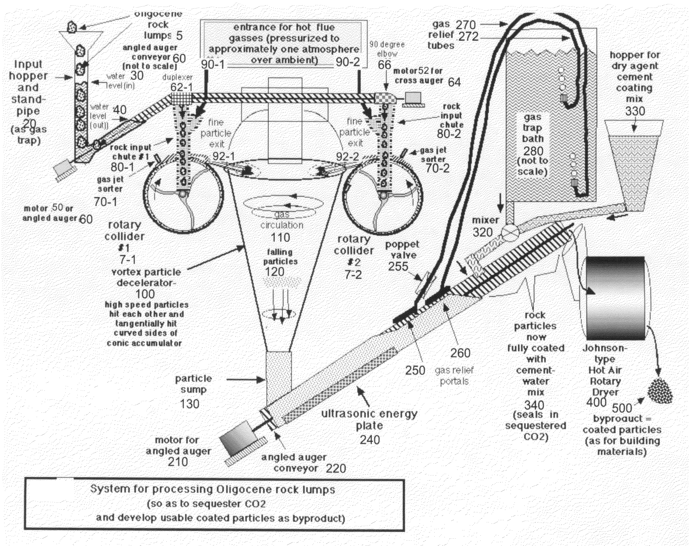
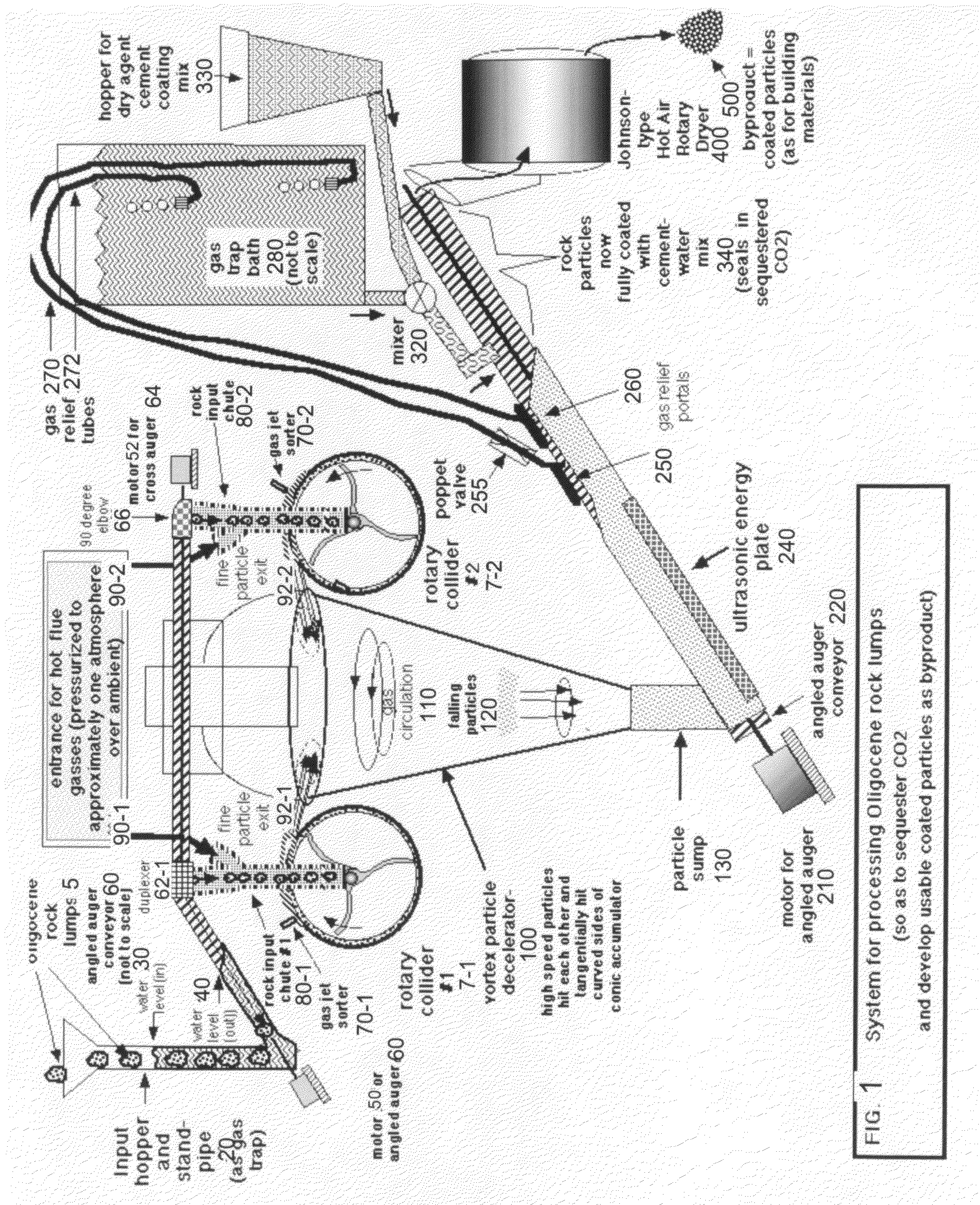
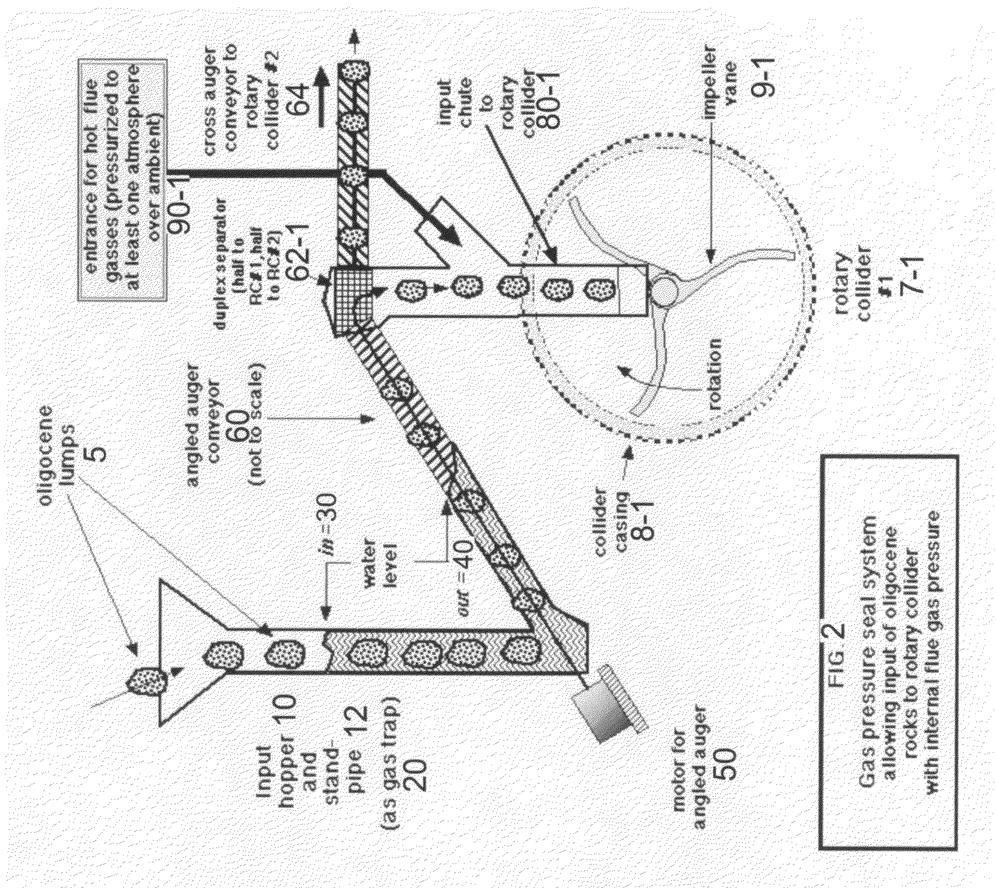
[0062]Viewing FIG. 1, the Oligocene rock lump input station 20 is at upper left. and consists of a input hopper and standpipe, to be described in more detail when viewing FIG. 2. The standpipe in 20 is filled with water, whose weight will counterbalance the force of flue gas, as 90-1 which has pressurized both the leftmost rotary collider 7-1 and the rightmost rotary collider 7-2.

[0063]The rightmost rotary collider 7-1 has its ejecta exit (fine particle exit 92-1) facing rightward, and the leftmost rotary collider 70-2 has its ejecta exit (fine particle exit 92-1) facing left, both ejecting particles into the vortex particle decelerator 100 to be further described when viewing FIG. 3.

[0064]The remainder of the equipment in the rightmost portion of the schematic of FIG. 1 is utilized to subject the gathered fine particles in the vortex sump 130 to ultrasonic energy from ultrasonic energy plate 240, and to vent any remaining gasses to a gas trap bath 280, before coating the particles ...


PUM

PropertyMeasurementUnit
sizeaaaaaaaaaa
diameteraaaaaaaaaa
diameteraaaaaaaaaa

Abstract

Coal burning waste gases, notably carbon dioxide (CO2), can be removed or sequestered, and the distribution and utilization of coal as a safe, efficient, and convenient heat source can be improved.Carbon dioxide, a waste gas as from a coal burning process, can be sequestered within freshly fractured rock particles, such as Oligocene rock serpentine, using an adapted version of a rotary collider to fracture down hens-egg sized incoming rocks in a pressurized waste gas. The process sorts the small, fractured rocks and coats them after CO2 sequestration with a cementitious coating for use as a component of building material.In order to improve the transport and delivery of mined coal it is an advantage to fracture the coal and coat the particles with an aqueous liquid. The methods and apparatus deal with the improved delivery of said liquid-coated coal particles for current and new customers who become interested in using coal as an economical heating fuel.

Description

CROSS REFERENCE TO RELATED APPLICATIONS[0001]Applicant claims priority of the following provisional applications, for each of which he is the inventor:[0002]a. Versatile System for Coal Purification, Coating, Transport, Storage, Recycling, and Distributed Use by Households and Small and Medium Sized Power PlantsFiling Date: May 26, 2006Application #: U.S. 60 / 808,672[0003]b. System for Efficient Sequestration of Carbon DioxideFiling Date: Feb. 1, 2007Application #: U.S. 60 / 898,672[0004]c. Fractured Oligocene Particles for Carbon Dioxide Waste Gas Sequestration SystemFiling Date: Apr. 23, 2007Application #: U.S. 60 / 925,6681. BACKGROUND OF THE INVENTION[0005]The US has large reserves of coal, both bituminous and anthracitic, but has very little petroleum reserves. There are some reserves of natural gas, but these are not large enough to supply the need to generate heat and electricity, or more particularly, not enough to supply vehicular fuel needs. Thus, the US imports vast quantities...

Claims


Application Information

Patent Timeline
Patent Type & Authority Applications(United States)
IPC IPC(8): E21C41/00B07C5/04E21C37/00E04B1/66
CPCB01D53/62B01D2251/402Y02C10/04F23K1/00C10L9/02B01D2251/602B01D2253/106B01D2257/504C04B20/1077C10L5/24C10L5/36C10L5/365C04B14/042C04B20/1022C04B2103/10Y02C20/40
Inventor LAHR, ROY JEREMY
Owner LAHR ROY JEREMY
Why Eureka
Try Eureka