Igniter voltage compensation circuit

a voltage compensation circuit and ignition circuit technology, applied in the field of circuits, can solve the problems of electrical and physical noise produced by the spark, hot surface-type ignition circuits, and require significant ignition/warm-up time, and achieve the effect of convenient switching

Inactive Publication Date: 2010-06-10
COORSTEK INC
View PDF71 Cites 12 Cited by
  • Summary
  • Abstract
  • Description
  • Claims
  • Application Information

AI Technical Summary

Benefits of technology

[0037]TRIAC: A triac or triode for alternating current shall be understood to be an electronic component approximately equivalent to two silicon-controlled rectifiers (SCRs / tyristors) joined in inverse parallel (paralleled but with the polarity reversed). Formal name for a Triac is bidirectional triode thyristor. This results in a bidirectional electronic switch which can conduct current in either direction when it is triggered (turned on). It can be triggered by either a positive or a negative voltage being applied to its gate electrode (with respect to A1, otherwise known as MT1). Once triggered, the device continues to conduct until the current through it drops below a certain threshold value, such as at the end of a half-cycle of alternating current (AC) mains power. This makes the triac a very convenient switch for AC circuits, allowing the control of very large power flows with milliampere-scale control currents. In addition, applying a trigger pulse at a controllable point in an AC cycle allows one to control the percentage of current that flows through the triac to the load (so-called phase control).

Problems solved by technology

Problems with spark-type igniters, however, include among other things the electronic and physical noise produced by the spark.
Hot surface-type igniters, however, can require significant ignition / warm-up time to resistively heated the resistance igniter sufficiently to a temperature that will ignite gas.
These lower and higher line or applied voltages, while not generally impacting the capability of the igniter to ignite the fuel mixture, can lead to the igniter having a shorter operational life than the case where the applied voltage was being maintained at a desired voltage.
In such cases, fluctuations in the line voltage can create conditions that affect the operational life of the igniter.
As is known to those skilled in the art, a chief disadvantage of this well known configuration is that the charging rate of the capacitor 18 is affected by the line voltage.
This further increase in igniter voltage further increases the igniter temperature and thus, tends to shorten its life.
This further reduction in igniter voltage correspondingly decreases the temperature of the igniter 2, which reduces in turn the igniter's effectiveness in achieving ignition.

Method used


Image

  • Igniter voltage compensation circuit
  • Igniter voltage compensation circuit
  • Igniter voltage compensation circuit

Examples


Embodiment Construction

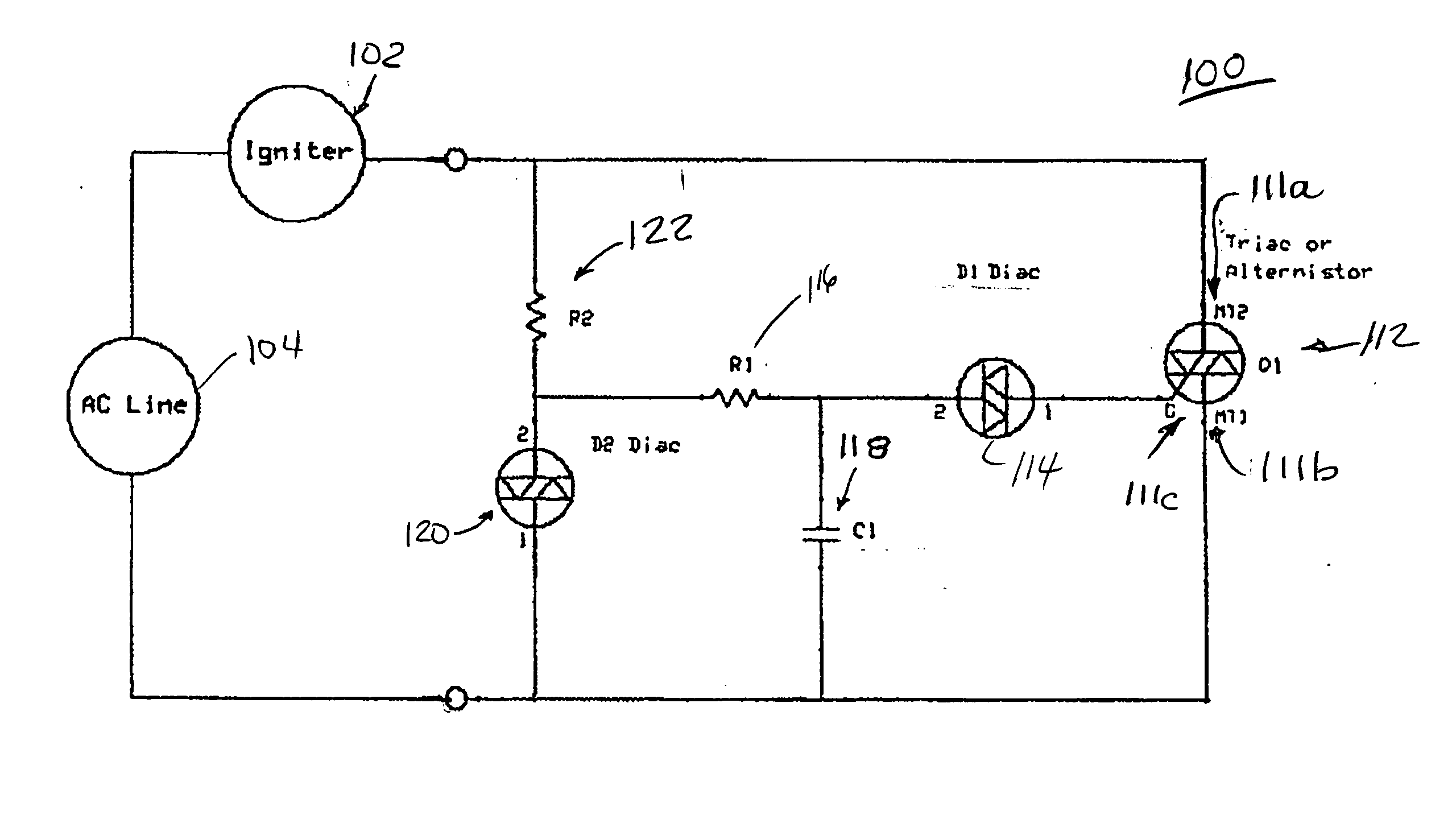
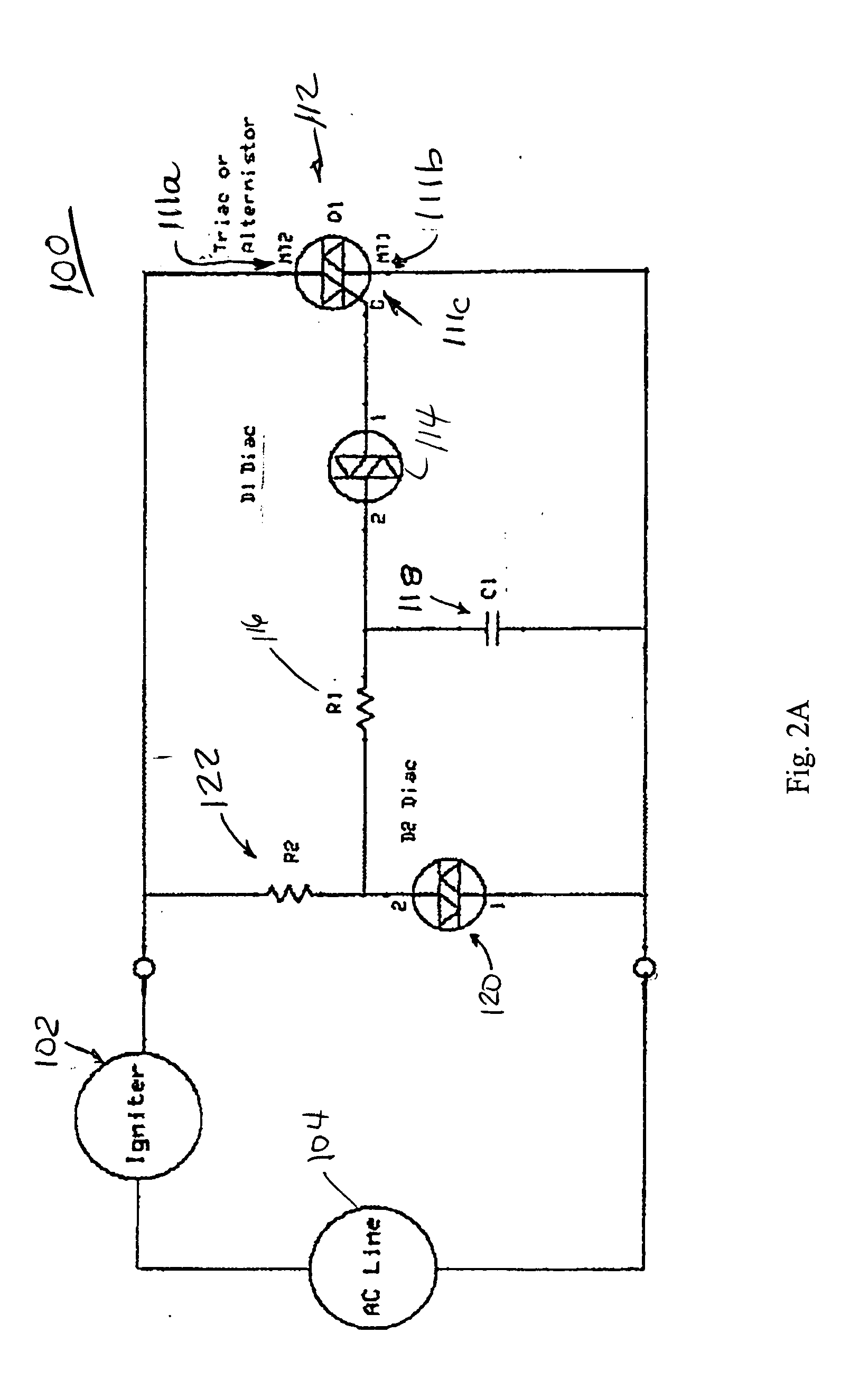
[0048]In one aspect of the present invention, the present invention features an igniter control circuit 100 that reduces the line voltage to an igniter 102 and which maintains the igniter voltage relatively stable. More particularly, there is featured a thyristor-based phase control circuit that reduces the RMS voltage being applied to an igniter 102 when it is connected to the AC line 104 or line voltage. Such an igniter control circuit 100 also is configured so that it opposes changes in line voltage such that the igniter voltage remains relatively stable when the line voltage increases or decreases relative to its nominal level.

[0049]Referring now to the various figures of the drawing wherein like reference characters refer to like parts, there is a shown in FIG. 2A a schematic view of a thyristor-based phase control circuit 100, more particularly a Dual-Diac thyristor-based phase control circuit, for an igniter 102 according to the present invention. Such a control circuit 100 r...


PUM


Abstract

Featured is igniter control circuitry that reduces the line voltage to the igniter and which maintains the igniter voltage relatively stable. More particularly, there is featured, a thyristor-based phase control circuit that reduces the RMS voltage being applied to an igniter when it is connected to the AC line or line voltage. The circuitry also is configured so that it opposes changes in line voltage such that the igniter voltage remains relatively stable when the line voltage increases or decreases relative to its nominal level. Such control circuitry includes a dual diac configuration, a relation oscillator configuration and one embodying both dual diac and relation oscillator configurations.

Description

[0001]This application claims the benefit of U.S. Provisional Application Ser. No. 61 / 118,631 filed Nov. 30, 2008, the teachings of which are incorporated herein by reference.FIELD OF INVENTION[0002]The present invention generally relates to circuitry, systems and methods for controlling ignition of combustible material such as natural gas or propane, more particularly to circuitry for controlling ignition (including re-ignition of gas) when using electrical resistance igniters, even more particularly to circuitry for controlling the voltage being applied to the electrical resistance igniter.BACKGROUND OF THE INVENTION[0003]There are a number of appliances such as cooking ranges and clothes dryers, water heaters and furnaces in which a combustible material, such as a combustible hydrocarbon (e.g., propane, natural gas) is mixed with air (i.e., oxygen) and continuously combusted within the appliance, water heater or furnace so as to provide a continuous source of heat energy. This co...

Claims


Application Information

Patent Timeline
Patent Type & Authority Applications(United States)
IPC IPC(8): G05F3/04
CPCF02P3/08F23N2027/28H03K17/725H02P7/2925H02M5/2573F23N2227/28H02P7/293
Inventor DUCHENE, GLENN A.
Owner COORSTEK INC
Why Eureka
Try Eureka