Semiconductor laser with low relative intensity noise of individual longitudinal modes and optical transmission system incorporating the laser

a diode laser and semiconductor technology, applied in the field of semiconductor diode lasers, can solve the problems of high cost, large footprint, and difficulty in building arrays of single-frequency lasers, and achieve the effects of low relative intensity noise (rin), low bit error rate, and high efficiency

Active Publication Date: 2010-06-10
INNOLUME
View PDF99 Cites 18 Cited by
  • Summary
  • Abstract
  • Description
  • Claims
  • Application Information

AI Technical Summary

Benefits of technology

[0008]A multimode edge-emitting semiconductor laser has low relative intensity noise (RIN) of individual longitudinal modes. The active region of the laser is based on an inhomogeneously broadened array of self-organized quantum dots (QDs). The laser includes an active section and at least one integrated noise reducing section, where the active section and the noise reducing sections are electrically isolated. The noise reducing section provides mode coupling and synchronization.
[0009]The laser emits a plurality of optical modes such that the relative intensity noise of each optical mode is less than 0.2% in the 0.001 GHz to 10 GHz range. In one embodiment, the average optical power per channel is more than 2 mW. The RIN of each longitudinal mode is sufficient to obtain a low bit error rate at high modulation speeds.
[0010]In another embodiment, the total RIN is less than 0.1% for at least ten optical modes. In yet another embodiment, the total RIN is less than 0.2% for at least 48 optical modes, and their intensity distribution is very uniform and varies by 30% or less.
[0011]In a preferred embodiment, the longitudinal modes are used as independent information channels in a multi-channel optical transmission system. An optical transmission system includes at least one laser that provides a plurality of low RIN optical ...

Problems solved by technology

The complexity of fabrication of a DFB laser 901 results in its high cost, which is further multiplied by the number of lasers 901 to be integrated.
This makes it difficult to build an array of single-frequency lasers 901 with pre-se...

Method used


Image

  • Semiconductor laser with low relative intensity noise of individual longitudinal modes and optical transmission system incorporating the laser
  • Semiconductor laser with low relative intensity noise of individual longitudinal modes and optical transmission system incorporating the laser
  • Semiconductor laser with low relative intensity noise of individual longitudinal modes and optical transmission system incorporating the laser

Examples


examples

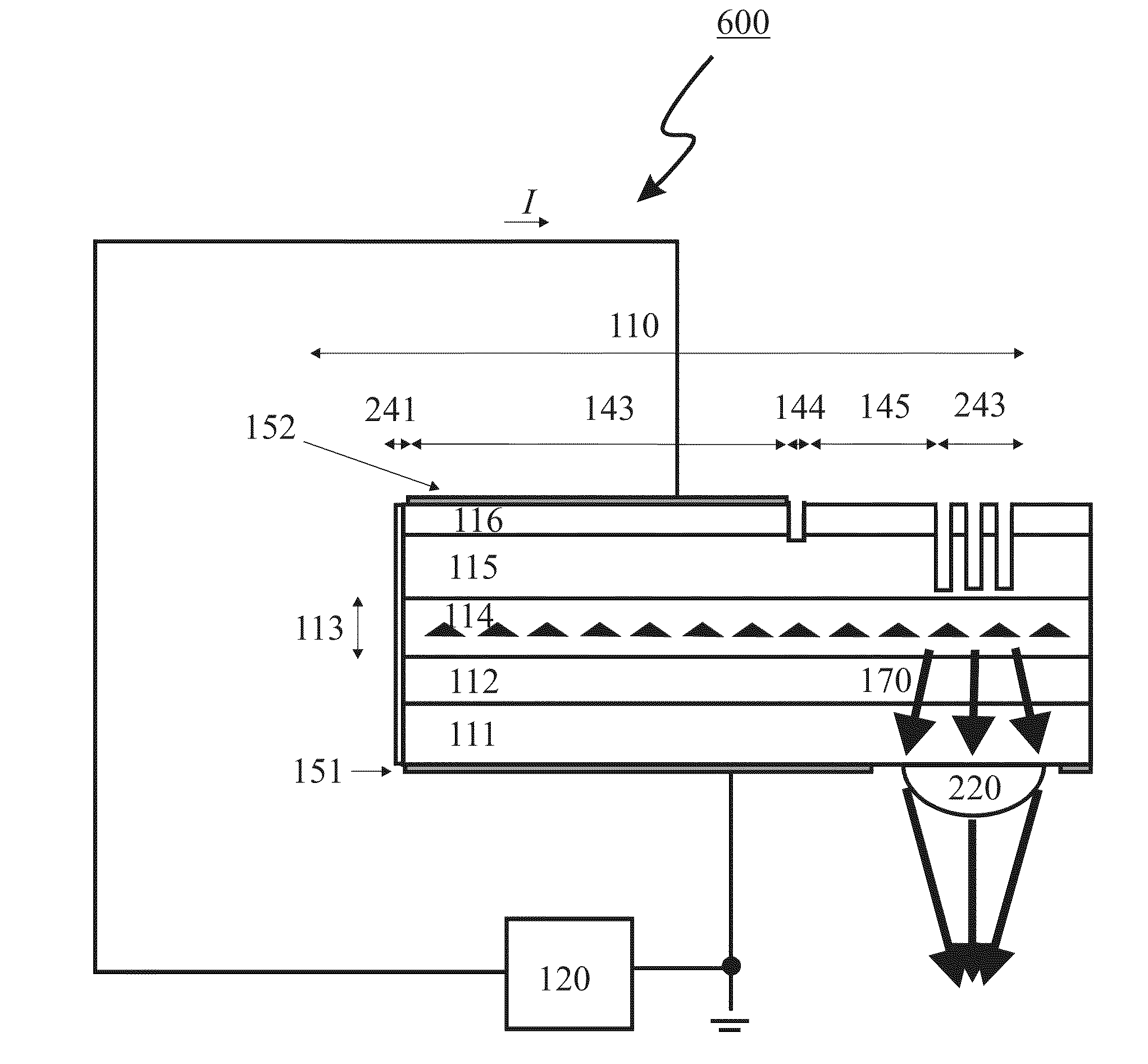
[0108]In one example, the laser active region represents ten identical planes of self-organized quantum dots. Each quantum dot plane was formed by epitaxial deposition of 0.8 nm-thick InAs insertions covered with In0.15Ga0.85As capping layers and embedded into a GaAs matrix. The laser structure has a 0.44 μm-thick GaAs / Al0.25Ga0.75As waveguide. The laser represents an edge-emitting Fabry-Perot laser in a pigtailed package. A pigtailed package is a standard laser package having an optical fiber for outputting the laser radiation. The epitaxial wafer was processed into ridge lasers. The active section length was 690 μm and the integrated noise reducing section length was varied within the range of 50-150 μm. The front mirror was as cleaved, and a high reflection coating (99% reflectivity) was formed on the back mirror. An important difference between this device and the device described in U.S. patent application Ser. No. 11 / 938,472 and Gubenko et al. is the noise reducing section.

[01...


PUM


Abstract

A semiconductor laser comprises an electrically isolated active section and at least one noise reducing section and operates on a ground state transition of a quantum dot array having inhomogeneous broadening greater than 10 nm. The laser preferably emits more than 10 optical modes such that a total relative intensity noise of each optical mode is less than 0.2% in the 0.001 GHz to 10 GHz range. The spectral power density is preferably higher than 2 mW/nm. An optical transmission system and a method of operating a quantum dot laser with low relative intensity noise of each optical mode are also disclosed.

Description

REFERENCE TO RELATED APPLICATIONS[0001]This application claims one or more inventions which were disclosed in Provisional Application No. 61 / 119,414, filed Dec. 3, 2008, entitled “SEMICONDUCTOR LASER WITH LOW RELATIVE INTENSITY NOISE OF INDIVIDUAL LONGITUDINAL MODES”. The benefit under 35 USC §119(e) of the U.S. provisional application is hereby claimed, and the aforementioned application is hereby incorporated herein by reference.[0002]This application is also a continuation-in-part of co-pending patent application Ser. No. 11 / 938,472, filed Nov. 12, 2007, entitled “OPTICAL TRANSMISSION SYSTEM, which claims one or more inventions which were disclosed in Provisional Application No. 60 / 867,952, filed Nov. 30, 2006, entitled “OPTICAL TRANSMISSION SYSTEM”, and is a continuation-in-part of patent application Ser. No. 11 / 295,943, filed Dec. 7, 2005, entitled “LASER SOURCE WITH BROADBAND SPECTRUM EMISSION”, now U.S. Pat. No. 7,561,607, issued Jul. 14, 2009, and patent application Ser. No....

Claims


Application Information

Patent Timeline
IPC IPC(8): H04B10/02H01S5/026H01S5/34H01S5/125
CPCB82Y20/00H01S5/0014H01S5/0078H01S5/0265H01S5/0625H01S5/0652H01S2301/02H01S5/125H01S5/16H01S5/187H01S5/341H01S5/3412H01S5/1096H01S5/1025
Inventor GUBENKO, ALEXEYKOVSH, ALEXEYWOJCIK, GREGLIVSHITS, DANIILKRESTNIKOV, IGORMIKHRIN, SERGEY
Owner INNOLUME
Why Eureka
Try Eureka