Articles for high temperature service and methods for their manufacture

a technology of high temperature service and manufacturing methods, applied in the direction of wind motors with parallel air flow, wind motors with perpendicular air flow, liquid fuel engine components, etc., can solve the problems of clogging of cooling holes and more expensive pvd techniques to adhere to critical cooling hole flow specifications

Active Publication Date: 2010-06-10
GENERAL ELECTRIC CO
View PDF8 Cites 32 Cited by
  • Summary
  • Abstract
  • Description
  • Claims
  • Application Information

AI Technical Summary

Benefits of technology

[0005]Embodiments of the present invention are provided to meet this and other needs. One embodiment is an article comprising a substrate comprising a top surface and a channel disposed in the substrate. The channel is defined by an internal channel surface disposed beneath the top surface and having a terminal end at an orifice at the top surface. A coating is disposed on the top surface and on at least a portion of the internal channel surface. A coating thickness at any point on the internal channel surface is less than a nominal coating thickness on the top surface, and the coating comprises a plurality of at least partially melted and solidified particles.
[0006]Another embodiment is a component for a tu

Problems solved by technology

Furthermore, such components often employ cooling systems that may include complex arrangements of internal cooling channels that receive air or other cooling fluid and circulate the fluid throughout the component to maintain its temperature at an acceptable level.
However, it is known that conventional APS techniques frequently produce clogging of cooling hol

Method used


Image

  • Articles for high temperature service and methods for their manufacture
  • Articles for high temperature service and methods for their manufacture
  • Articles for high temperature service and methods for their manufacture

Examples


example 1

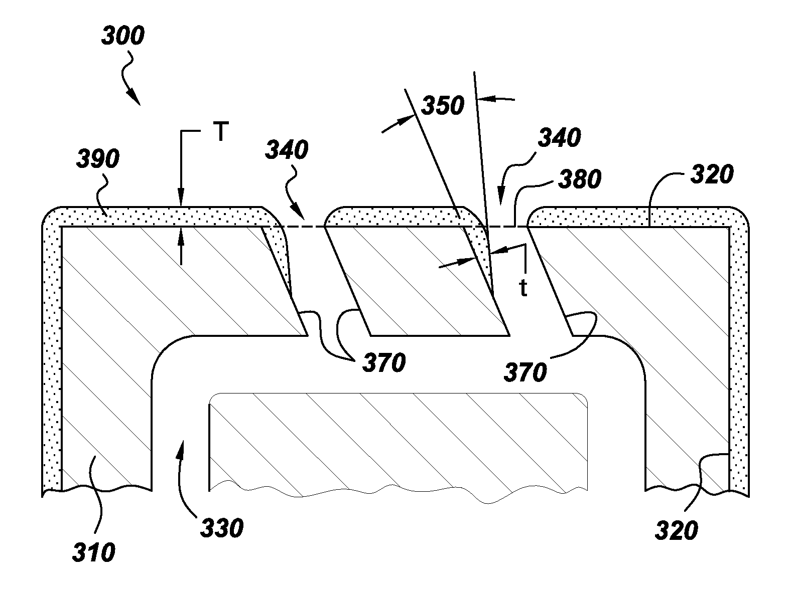
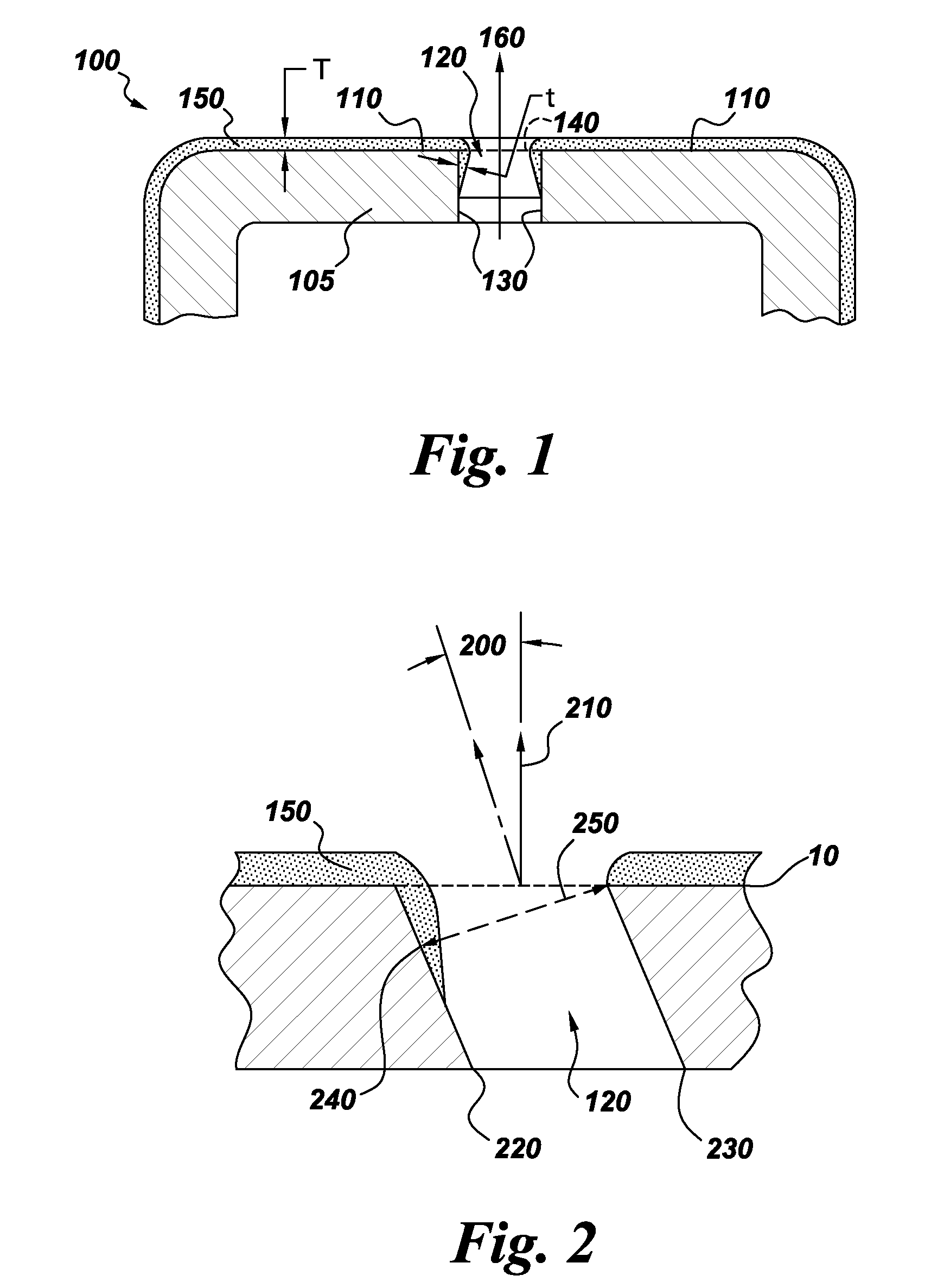
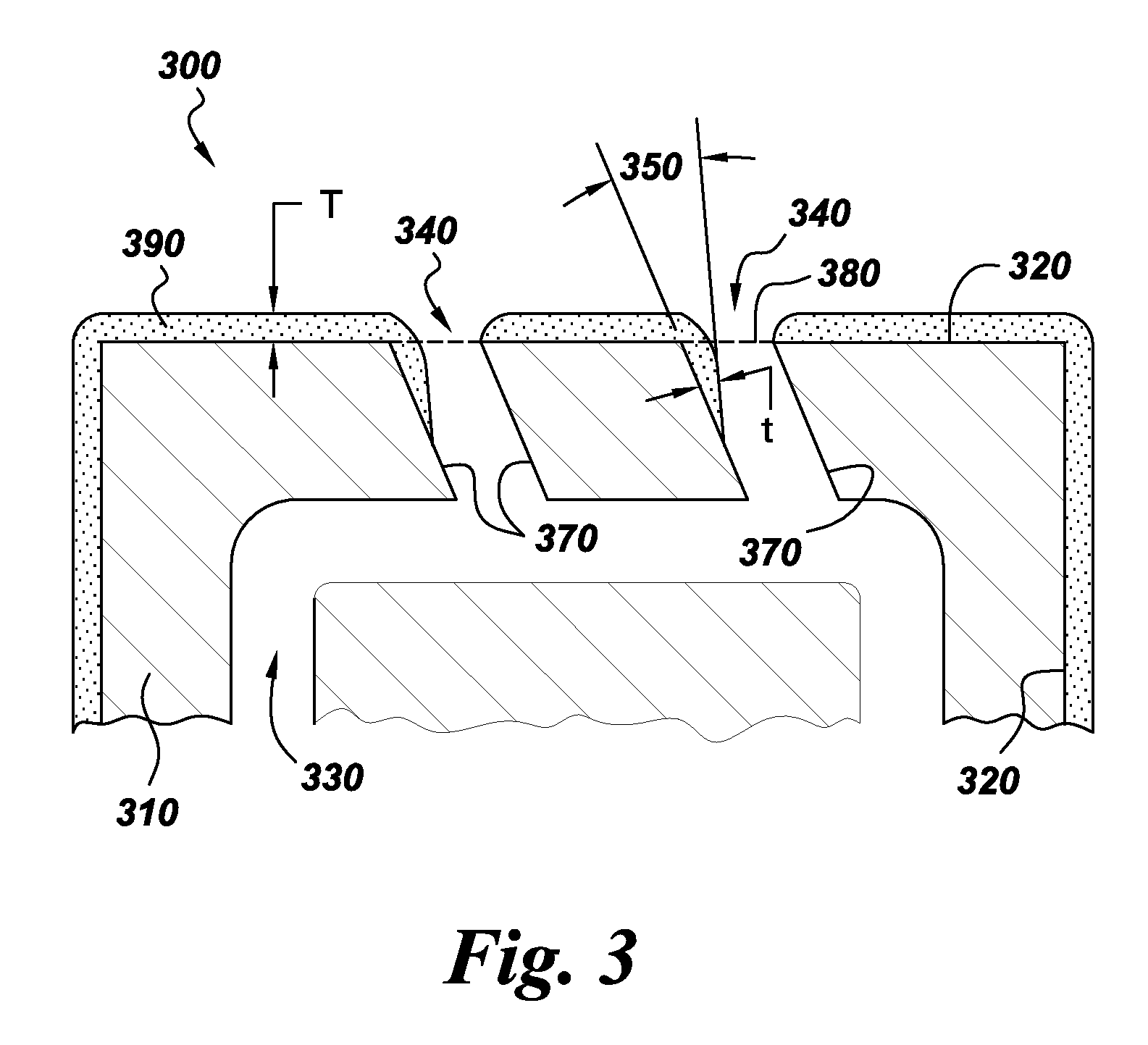
[0025]An yttria-stabilized-zirconia (YSZ) coating was produced on a nominal 1.6 millimeter thick plate of a cobalt-based superalloy substrate using a Mettech Axial III DC plasma torch. Prior to coating deposition, the substrate was laser drilled to obtain 10 rows of 10 through holes each of nominally 508 micron (0.020 inch) diameter at an angle of 30 degrees relative to the top surface of the plate. Each laser drilled hole was spaced approximately 3 mm from an adjacent hole. The plate was deburred and abrasive blasted using 220 mesh aluminum oxide prior to coating. The feedstock material used to produce the coating was an 8 wt % YSZ powder with a d50 of 0.4 mm suspended in ethanol at 10 wt % using polyethyleneimine as a dispersant (at 0.2 wt % of the solids). The suspension was injected into the plasma torch through the center tube of a tube-in-tube atomizing injector with a nitrogen atomizing gas sent through the outer tube. The torch power was about 90 kW using an electrode curren...

example 2

[0027]As in example 1, a YSZ coating was deposited onto a similarly prepared laser drilled cobalt alloy plate. Feedstock was the same as in example 1. Plasma parameters used to produce coatings in this example were a total torch power of 90 kW obtained using an electrode current of 200 amps per electrode and a total plasma gas flow of 245 slpm consisting of 75% argon, 10% nitrogen, and 15% hydrogen. The plasma torch was rastered across the substrate at 600 mm / sec while maintaining a constant spray distance of 76 mm distance between the torch nozzle and substrate. An average coating thickness of 100 micrometers was obtained on the top surface of the plate. As in example 1, a tapered coating profile was produced from the top coated surface extending into the holes. The coating thickness measured at the throat threshold of the hole was 4% of the channel diameter.

example 3

[0028]Plasma parameters were the same as in example 2, except that a spray distance of 50 millimeters was used. An average coating thickness of 140 micrometers was obtained on the top surface of the plate. As in examples 1 and 2, a tapered coating profile was produced from the top coated surface extending into the holes. The coating thickness measured at the throat threshold of the hole was 9% of the channel diameter.


PUM

PropertyMeasurementUnit
Fractionaaaaaaaaaa
Fractionaaaaaaaaaa
Fractionaaaaaaaaaa

Abstract

Articles coated via a plasma spray process, and methods for making such articles, are presented. For example, one embodiment is an article comprising a substrate comprising a top surface and a channel disposed in the substrate. The channel is defined by an internal channel surface disposed beneath the top surface and having a terminal end at an orifice at the top surface. A coating is disposed on the top surface and on at least a portion of the internal channel surface. A coating thickness at any point on the internal channel surface is less than a nominal coating thickness on the top surface, and the coating comprises a plurality of at least partially melted and solidified particles.

Description

BACKGROUND[0001]This invention relates to high-temperature machine components. More particularly, this invention relates to coating systems for protecting machine components from exposure to high-temperature environments. This invention also relates to methods for protecting articles.[0002]The components of gas turbine assemblies and other industrial equipment can be exposed to gas temperatures in excess of 1350° C. Accordingly, such components are designed to reliably perform their functions within this aggressive service environment, often employing a combination of strategies to prolong nominal service time at temperature. For instance, high temperature materials such as superalloys are often employed in turbine assembly components exposed to the flow of hot gas. Additionally, thermal barrier coating systems, generally comprising an oxidation-resistant metallic “bondcoat” disposed on the component surface and a heat-resistant ceramic “topcoat” disposed over the bondcoat, are ofte...

Claims


Application Information

Patent Timeline
IPC IPC(8): B32B3/00B05D1/02F01D5/28F01D9/02
CPCC23C4/005F01D5/005F01D5/186F01D5/288F05D2230/90Y10T428/24521Y10T428/256Y10T428/24612Y10T428/24479Y10T428/25F05D2230/80C23C4/01
Inventor ROSENZWEIG, LARRY STEVENRUUD, JAMES ANTHONYMANOHARAN, MOHANPILSNER, BRIAN HARVEY
Owner GENERAL ELECTRIC CO
Why Eureka
Try Eureka