Systems and Methods of Laser Texturing of Material Surfaces and their Applications

a technology of material surface and laser texturing, which is applied in the field of laser texturing of material surface and its application, can solve the problems of surface properties changing and surface properties changing, and achieve the effects of reducing surface roughness, improving surface texture, and improving surface textur

Inactive Publication Date: 2010-06-10
UNIV OF VIRGINIA ALUMNI PATENTS FOUND
View PDF46 Cites 101 Cited by
  • Summary
  • Abstract
  • Description
  • Claims
  • Application Information

AI Technical Summary

Benefits of technology

[0029]An aspect of an embodiment of the present invention provides, but not limited thereto, a surface of a material that is textured and by exposing the surface to pulses from an ultrafast laser (or other desired energy source). The laser treatment causes pillars to form on the treated surface. These pillars provide for greater light absorption. Texturing and crystallization can be carried out as a single step process. The crystallization of the material provides for higher electric conductivity and changes in optical and electronic properties of the material. The method may be performed in vacuum or a gaseous environment. The gaseous environment may aid in texturing and / or modifying physical and chemical properties of the surfaces. This method may be used on various material surfaces, such as but not limited thereto, semiconductors, metals and their alloys, ceramics, polymers, glasses, composites, as well as crystalline, nanocrystalline, polycrystalline, microcrystalline, and amorphous phases. The related method may be used to provide a variety material surfaces or templates for a variety of systems and devices.

Problems solved by technology

This method produces a periodic array of pillar structures on the surface, resulting in changes in properties of the surface.
This method produces pillar structures on the surface, resulting in changes in properties of the surface.

Method used


Image

  • Systems and Methods of Laser Texturing of Material Surfaces and their Applications
  • Systems and Methods of Laser Texturing of Material Surfaces and their Applications
  • Systems and Methods of Laser Texturing of Material Surfaces and their Applications

Examples


Embodiment Construction

[0071]In describing an exemplary embodiment of the present invention illustrated in the drawings, certain specific terminology will be used for the sake of clarity. However, the invention is not intended to be limited to that specific terminology, and it is to be understood that the terminology includes all technical equivalents that operate in a similar manner to accomplish the same or a similar result.

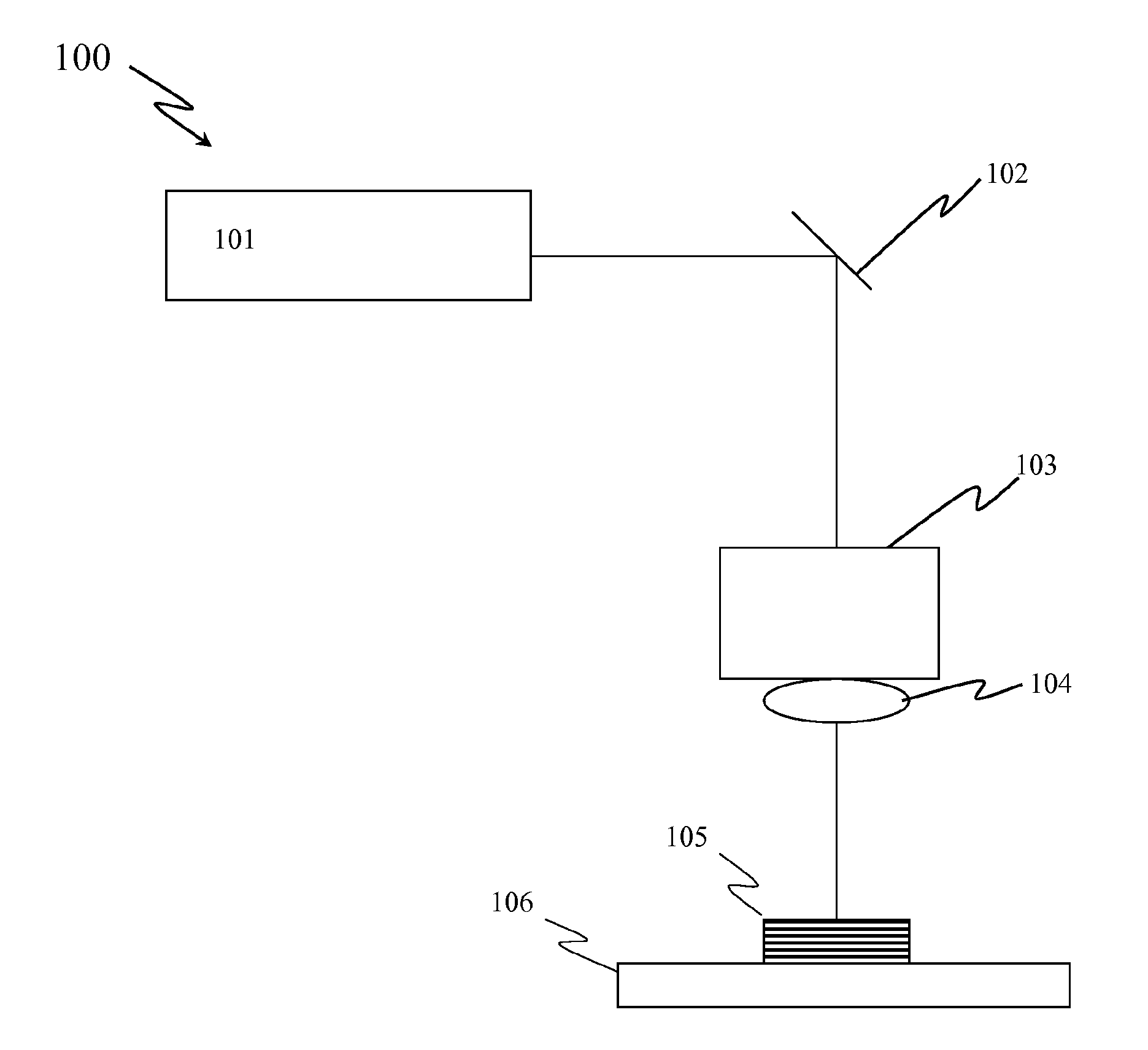
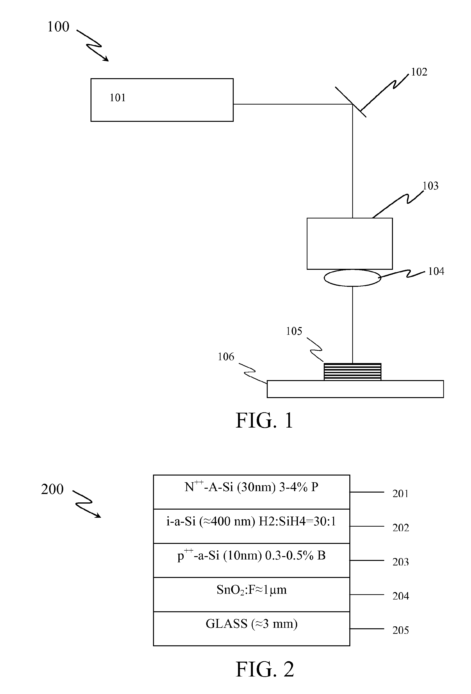
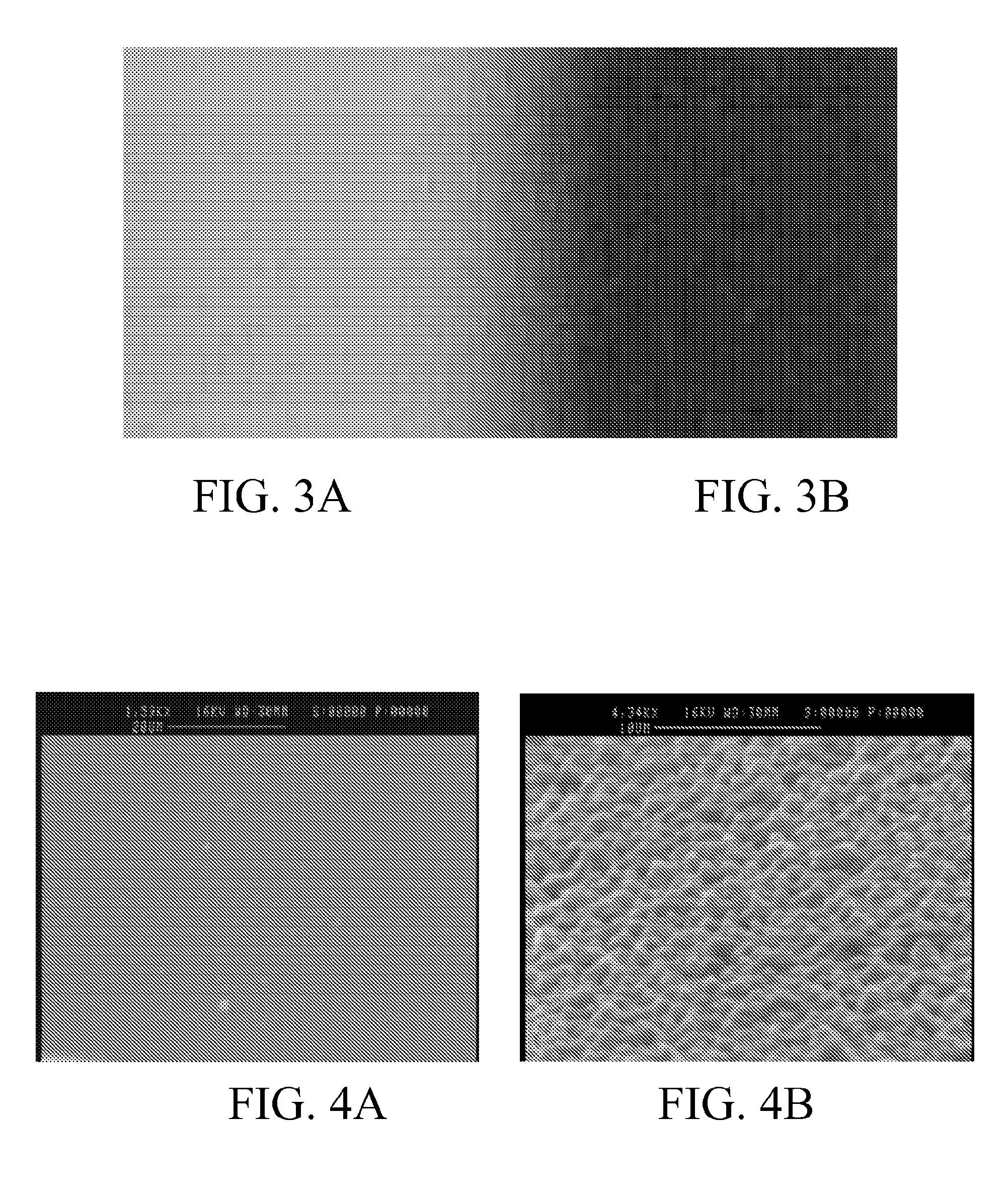
[0072]Apparatuses and methods consistent with the present invention texture and crystallize the surface of a material in one step by exposing the surface of the material to an ultrafast laser. In order to expose an area of the surface that is larger than the beam spot size, the material may be translated relative to the laser. The texturing causes pillars to form on the surface of the material, increasing the light absorption of the treated material. Pillars are height variations over a surface, including valleys and hills. Pillars can be formed in a variety of shapes, including coni...


PUM

PropertyMeasurementUnit
wavelengthaaaaaaaaaa
pressureaaaaaaaaaa

Abstract

The surface of a material is textured and by exposing the surface to pulses from an ultrafast laser. The laser treatment causes pillars to form on the treated surface. These pillars provide for greater light absorption. Texturing and crystallization can be carried out as a single step process. The crystallization of the material provides for higher electric conductivity and changes in optical and electronic properties of the material. The method may be performed in vacuum or a gaseous environment. The gaseous environment may aid in texturing and / or modifying physical and chemical properties of the surfaces. This method may be used on various material surfaces, such as semiconductors, metals and their alloys, ceramics, polymers, glasses, composites, as well as crystalline, nanocrystalline, polycrystalline, microcrystalline, and amorphous phases.

Description

CROSS-REFERENCE TO RELATED APPLICATIONS[0001]This application claims benefit of priority from U.S. Provisional Patent Application No. 60 / 905,808, filed on Mar. 9, 2007, entitled “Formation of Nano-Textured Conical Microstructures in Titanium, Fabrication of Superhydrophobic Surfaces and Fabrication of Nanopores in Silicon by Femtosecond Laser Irradiation.” The full disclosure of this provisional applications is incorporated herein by reference.[0002]This application is related to PCT International Application Serial No. PCT / US2006 / 049065, filed Dec. 21, 2006, entitled, “Systems And Methods of Laser Texturing and Crystallization of Material Surfaces,” which claims benefit of priority from U.S. Provisional Patent Application No. 60 / 752,545, filed on Dec. 21, 2005; U.S. Provisional Patent Application No. 60 / 843,874, filed on Sep. 12, 2006; and U.S. Provisional Patent Application No. 60 / 860,735, filed on Nov. 22, 2006. The full disclosures of this International Application and these Pro...

Claims


Application Information

Patent Timeline
Patent Type & Authority Applications(United States)
IPC IPC(8): B32B3/30H01L21/302B32B15/00C23F1/00H01L21/306H01L21/3065H01L31/0236H01L31/18H01L29/00
CPCB23K26/0009Y10T428/12396B23K26/0045B23K26/0048B23K26/0084B82Y20/00G02B6/1225H01L21/02422H01L21/02532H01L21/02587H01L21/02686H01L31/0236Y02E10/50Y10T428/24479B23K26/0036B23K26/0006B23K26/355B23K2103/16B23K2103/42B23K2103/50B23K2103/52
Inventor GUPTA, MOOL C.NAYAK, BARADA K.
Owner UNIV OF VIRGINIA ALUMNI PATENTS FOUND
Why Eureka
Try Eureka