Nonwoven fabric for filters

a technology of nonwoven fabric and filter, which is applied in the direction of weaving, separation process, filtration separation, etc., can solve the problems of insufficient collection capability of conventional thermo-compression type long fiber nonwoven fabrics, insufficient collection of obtained nonwoven fabrics that cannot sufficiently collect dust particles with particle sizes smaller than several micrometers, etc., to achieve excellent mechanical strength and thermal stability, excellent dust collection performan

Active Publication Date: 2010-06-17
TORAY IND INC
View PDF23 Cites 18 Cited by
  • Summary
  • Abstract
  • Description
  • Claims
  • Application Information

AI Technical Summary

Benefits of technology

[0024]This invention can provide a nonwoven fabric for filters excellent in mechanical strength and thermal stability and also excellent in dust collection performance.

Problems solved by technology

However, the conventional thermo-compression type long fiber nonwoven fabrics do not have sufficient collection capability, since the fiber diameters of the fibers constituting the nonwoven fabrics are about 10 μm at the smallest.
According to the technique, the nonwoven fabric for filters can have better mechanical properties and higher dimensional stability, but it cannot sufficiently collect dust particles with particle sizes smaller than several micrometers, since the fiber diameter of the component fibers is 2 to 15 decitex (dtex), that is, about 13 μm at the smallest.
However, since the proposed nonwoven fabric is obtained by laminating and integrating a nonwoven fabric with a fiber diameter of 7 to 20 μm and a nonwoven fabric with a fiber diameter of 20 to 50 μm, etc., the obtained nonwoven fabric cannot sufficiently collect dust particles with particle sizes smaller than several micrometers.
However, this technique has such problems that since the ultra-fine fibers do not contribute to the integration of the nonwoven fabric at all, the ultra-fine fibers are liable to come off from the nonwoven fabric and that the rate of ultra-fine fibers cannot be made high.
Furthermore, this technique is not excellent in view of productivity either, since the ultra-fine fibers are obtained by treating a nonwoven fabric likely to be split into ultra-fine fibers by a high pressure liquid flow, needle punching or buckling treatment.
However, since the nonwoven fabric provided by this technique has a unit area weight of about 10 to about 50 g / m2, it does not have the sufficient strength for allowing the use as an industrial filter.
So the production method is complicated.
However, the use of a polyester resin as the raw material has such a problem that since the polyester of the melt blown nonwoven fabric is often insufficient in oriented crystallization, the sheet is cured or remarkably shrunken in the case of thermal bonding.
Further, the use of the nonwoven fabric as a filter has such a problem that in a high temperature service environment, the sheet is cured or shrunken.
On the other hand, the use of a polyolefin resin as the raw material has such problems that heat resistance is low since the melting point is low, and that since the sheet is soft in touch the use of it especially as a pleated filter is not preferred.
Moreover, in the case where the resin of the melt blown nonwoven fabric is different from that of the spunbonded nonwoven fabric there is a problem that since the compatibility between the resins is insufficient the integration by thermal bonding is difficult.[Patent reference 1] JP2001-276529A[Patent reference 2] JP2004-124317A[Patent reference 3] JP2001-248056A[Patent reference 4] JP2004-154760A

Method used

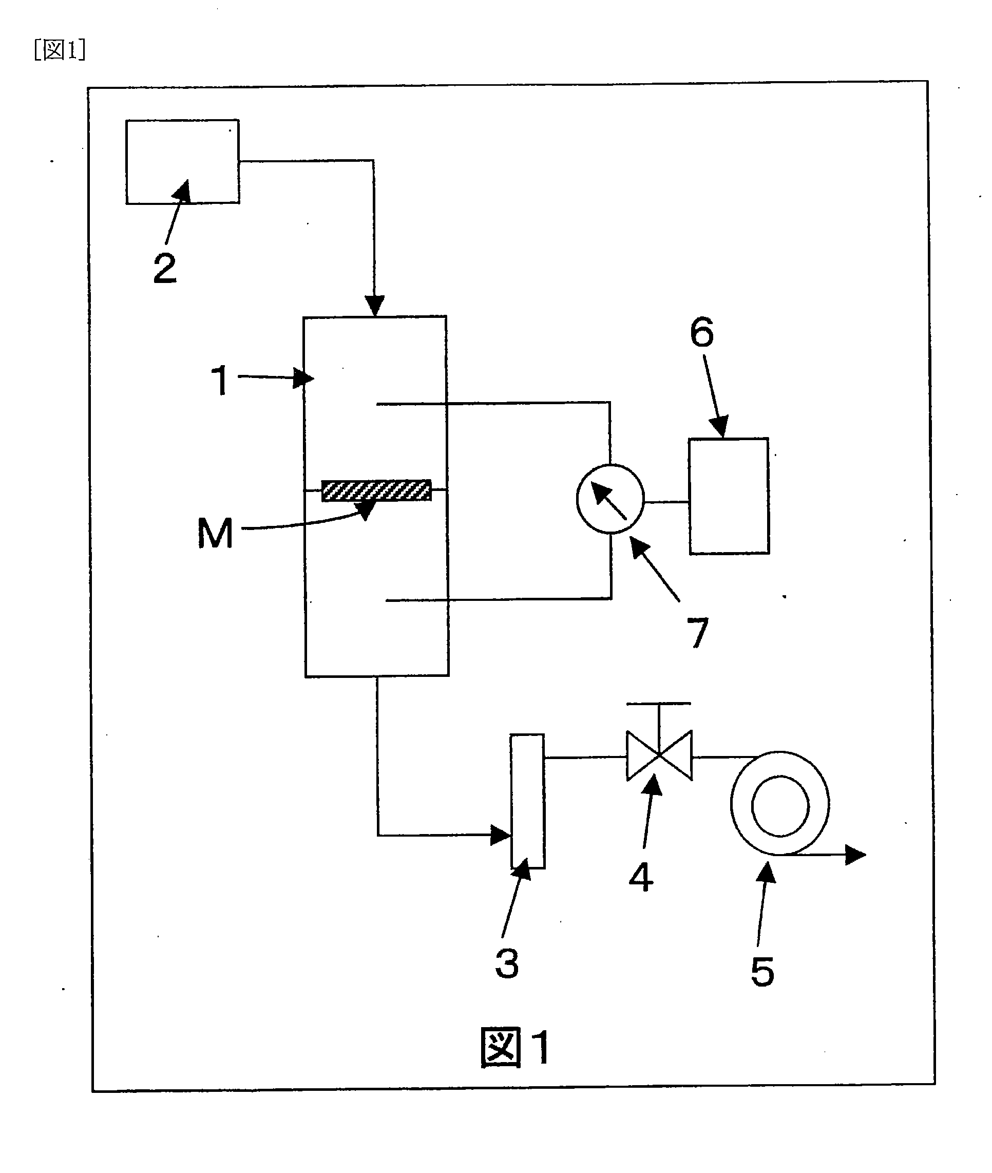

Image

  • Nonwoven fabric for filters
  • Nonwoven fabric for filters

Examples


production example 1

[0077]Polybutylene terephthalate (PBT) with a melt viscosity of 390 poises and a melting point of 221° C. dried to a water content of 80 wt ppm or less was molten at 280° C., and the hot air volume and the cooling conditions were adjusted to achieve an average fiber diameter of 2 μm at a die temperature of 280° C. and a heating air temperature of 285° C., for producing a melt blown nonwoven fabric with a unit area weight of 30 g / m2.

production example 2

[0078]Polytrimethylene terephthalate (PPT) with a melt viscosity of 500 poises and a melting point of 232° C. dried to a water content of 80 wt ppm or less was molten at 280° C., and the hot air volume and the cooling conditions were adjusted to achieve an average fiber diameter of 5 μm at a die temperature of 280° C. and a heating air temperature of 285° C., for producing a melt blown nonwoven fabric with a unit area weight of 30 g / m2.

production example 3

[0081]Polyethylene terephthalate (PET) with a melt viscosity of 800 poises and a melting point of 260° C. dried to a water content of 80 wt ppm or less was molten at 295° C., and a copolyester (CO-PET) having an isophthalic acid copolymerization rate of 11 mol %, with a melt viscosity of 420 poises and a melting point of 230° C. dried to a water content of 80 wt ppm or less was molten at 280° C. With the polyethylene terephthalate as the core component and the copolyester as the sheath component, they were discharged at a die temperature of 300° C. from pores at a ratio by weight of core:sheath=80:20, spun by an ejector at a spinning rate of 4400 m / min, and the fibers were collected on a moving net conveyor, for obtaining a web. The web was thermally compressed between an emboss roll with a projection area of 16% and a flat roll at a temperature of 140° C. and a linear pressure of 60 kg / cm, to produce a spunbonded nonwoven fabric with a fiber diameter of 12 μm and a unit area weight...


PUM

PropertyMeasurementUnit
diameteraaaaaaaaaa
diameteraaaaaaaaaa
diameteraaaaaaaaaa

Abstract

This invention relates to a nonwoven fabric for filters, in which a melt blown nonwoven fabric formed of polybutylene terephthalate or polypropylene terephthalate fibers with an average fiber diameter of 1 to 8 μm and a spunbonded nonwoven fabric formed of polyester-based fibers with an average fiber diameter of 10 to 30 μcm are laminated for integration.

Description

TECHNICAL FIELD[0001]The present invention relates to a nonwoven fabric for filters excellent in dust collection performance and also excellent in mechanical properties and dimensional stability.BACKGROUND ART[0002]Various nonwoven fabrics have been proposed as materials of air filters for removing dust and liquid filters. Especially in recent years, thermo-compression type long fiber nonwoven fabrics excellent in stiffness are suitably used as pleated filters. Pleated filters allow low filtration air velocities since they can have wide filtration areas, and have such advantages as higher dust collection capability and lower mechanical pressure loss.[0003]However, the conventional thermo-compression type long fiber nonwoven fabrics do not have sufficient collection capability, since the fiber diameters of the fibers constituting the nonwoven fabrics are about 10 μm at the smallest.[0004]For example, patent reference 1 proposes a composite long fiber nonwoven fabric for filters consi...

Claims


Application Information

Patent Timeline
Patent Type & Authority Applications(United States)
IPC IPC(8): B01D46/00B01D46/52B01D46/10B01D39/16B32B27/08B32B5/26
CPCB01D39/163B01D2239/0668Y10T428/24942B32B27/36D04H13/007B32B5/26D04H1/435D04H1/559D04H1/56D04H3/011D04H3/14Y10T442/62Y10T442/641Y10T442/66Y10T442/68Y10T442/681
Inventor TAKANO, NOBUYUKIITO, MASASHINISHIMURA, MAKOTO
Owner TORAY IND INC
Why Eureka
Try Eureka