Method for laser processing glass with a chamfered edge

a laser processing and edge technology, applied in glass making apparatus, manufacturing tools, welding/soldering/cutting articles, etc., can solve the problems of not having a method for creating a chamfer on the resulting edges in one manufacturing operation, not having a mechanical notch, etc., to achieve more control over the shape and size of the chamfer, and improve the quality of the finish. , the effect of improving the quality of the finish

Inactive Publication Date: 2010-06-17
ELECTRO SCI IND INC
View PDF31 Cites 81 Cited by
  • Summary
  • Abstract
  • Description
  • Claims
  • Application Information

AI Technical Summary

Benefits of technology

[0012]A further embodiment of the instant invention is shown in FIGS. 8a and b. In this embodiment the laser beam is moved along paths as shown in FIG. 4, however, the angle at which the laser impinges the material is varied with the location of the path on or in the material. FIG. 8a shows three representative laser beams and angles, with laser beam 110 at angle α1, laser beam 112 at angle α2 and laser beam 114 at angle αN, where N is an integer and angle αN>α2>α1. FIG. 8b shows a top-down view with one representative path 116 shown on the bulk material 118. The arrows, one of which is indicated 119, on the path indicate that the angle that the laser beam impinges the material 118 is always perpendicular to the path 116 as the article 117 is machined from the bulk material 118. The advantage of this approach is that it permits better control over the quality of the finish of the chamfer with fewer passes, but requires an apparatus that is able to control the angle of the laser beam with respect to the workpiece.
[0013]FIG. 9 shows a further embodiment of the instant invention. FIG. 9 is a side view showing laser beams 120, 122, and 124 impinging on bulk material 128. In this embodiment, the mechanism (not shown) moving the laser beam along a path with respect to the material does not change its path, rather the angle at which the laser beam is directed to the material is altered. The laser beam is pivoted about point 126 as it travels around a path on the bulk material 128, but only in a plane perpendicular to the path. This a

Problems solved by technology

While chamfered edges are desirable, no methods exist for creating an article with a chamfered edge in one manufacturing operation.
Such resultant stress and microcracks may either be sufficient to cause the glass to fracture and separate along the designed trajectories or may require a follow-up breaking step to separate the glass.
This technology, however, does require an initial mechanical

Method used


Image

  • Method for laser processing glass with a chamfered edge
  • Method for laser processing glass with a chamfered edge
  • Method for laser processing glass with a chamfered edge

Examples


Embodiment Construction

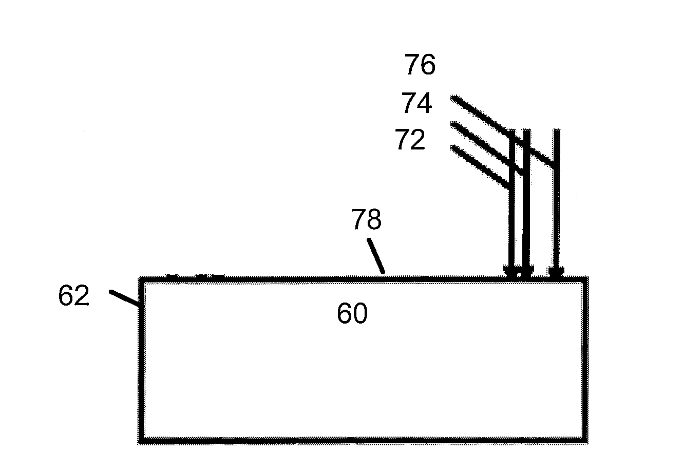
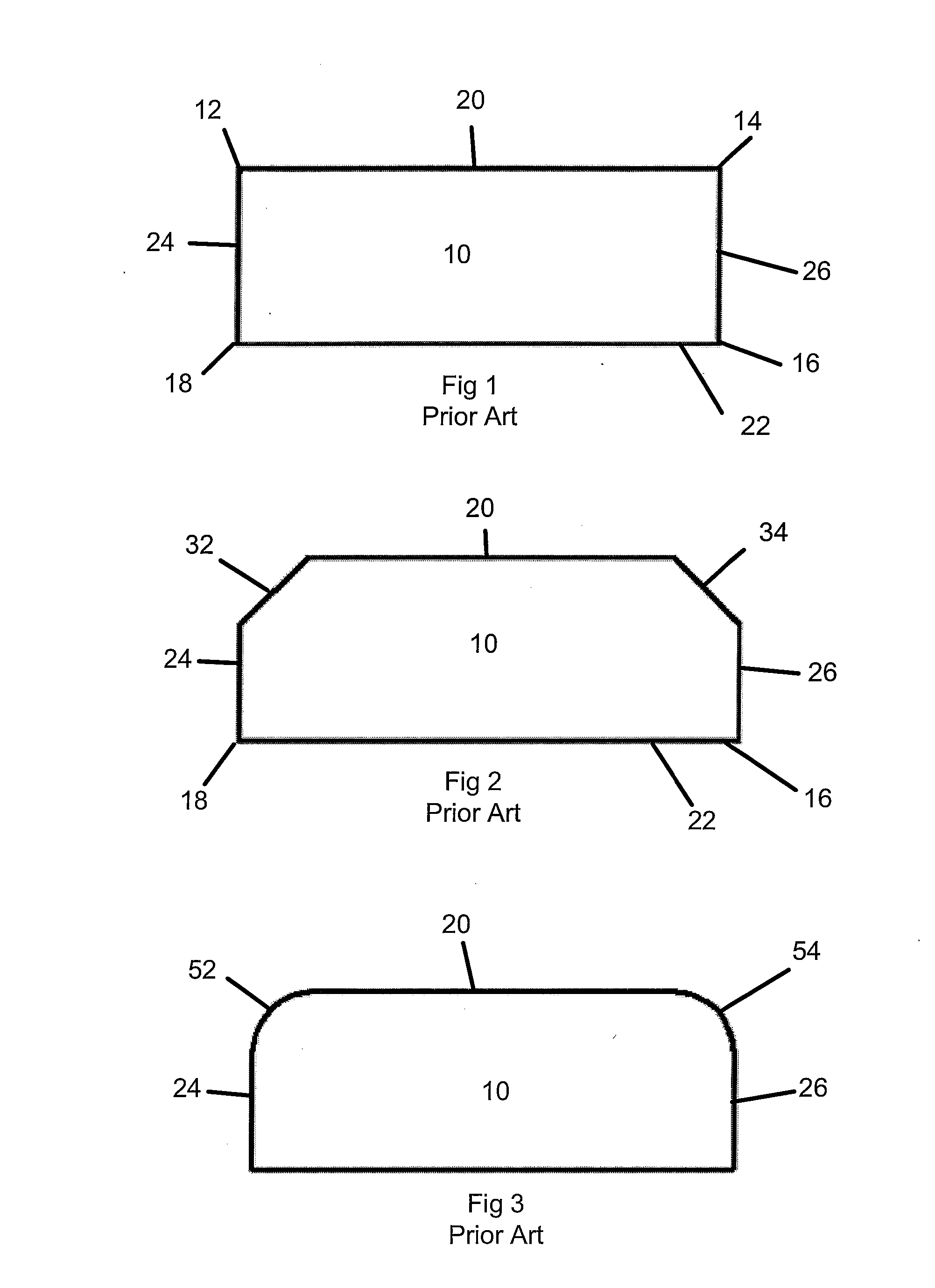
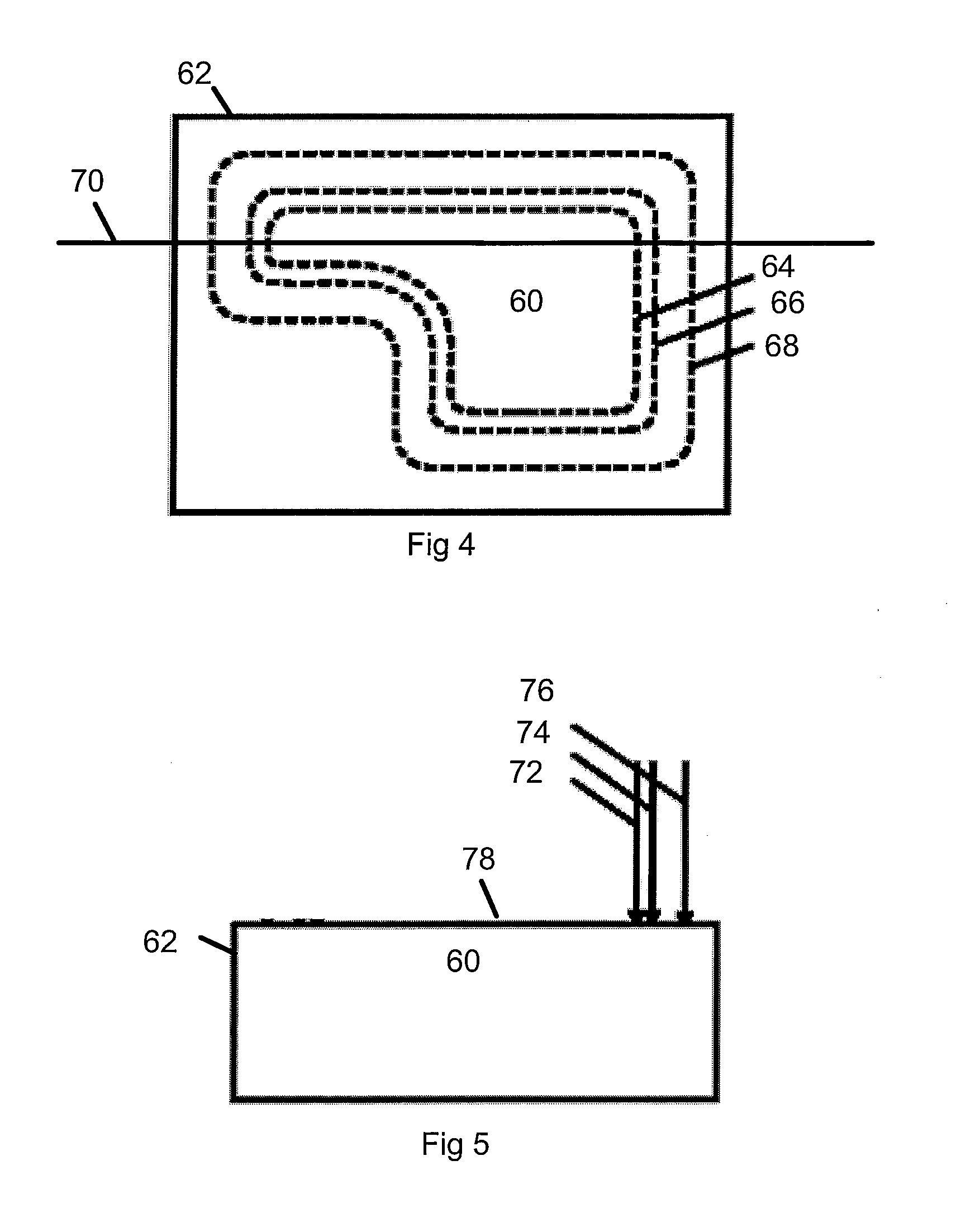
[0035]One of the goals of the instant invention is to permit laser machining of chamfered features in glass or glass-like materials in one manufacturing operation. An exemplary machine that can produce a and control a laser beam capable of ablating glass and glass-like materials, fixture the materials and move the laser beam(s) with respect to the material is the MM5800 laser micromachining system produced by Electro Scientific Industries, Inc., Portland, Oreg., the assignee of the instant invention.

[0036]The laser beam can be either continuous wave (CW) or pulsed. Laser parameters which are controlled to provide the desired ablation rate include wavelength, average power, spatial distribution, spot size and speed of travel. In the case of pulsed lasers, pulse width, pulse energy, pulse temporal distribution and repetition rate can be controlled to provide the desired ablation. Laser wavelengths can range from infrared (IR), such as 10.6 micron wavelengths emitted by CO2 lasers down...


PUM

PropertyMeasurementUnit
Angleaaaaaaaaaa
Transparencyaaaaaaaaaa

Abstract

A laser machining process is described for laser machining glass or glass-like materials. This process machines articles or features in articles with chamfered edges in one manufacturing operation. Chamfered edges are desirable in glass and glass-like materials because they resist fracturing or chipping and eliminate sharp edges. Producing articles or features in articles in one manufacturing operation is desirable because it can save time and expense by eliminating the need to transfer the article to a separate machine for chamfering after laser machining. Alternatively, it can permit use of less expensive equipment because the same laser used for machining can be used to form the chamfer instead of having a separate process perform the chamfering. Producing chamfers with laser machining results in high quality chamfers without the need for a separate polishing or finishing step.

Description

FIELD OF THE DISCLOSURE[0001]The field of the technical subject matter relates to laser machining glass or glass-like articles. In particular it relates to laser machining an article with a chamfer on an edge that adjoins the top or bottom surface of the article or on a feature laser machined into the article. In more particular it relates to laser machining glass or glass-like article with a chamfer in a single manufacturing operationBACKGROUND OF THE INVENTION[0002]Laser machining chamfered features in glass or glass-like articles such as sapphire, ceramic or glass ceramics is desirable because adding a chamfer to an edge makes the edge safer, in the sense that it is less likely to cause cuts or scratches when handled, makes it less likely to chip or crack and in general, makes the edge stronger. While chamfered edges are desirable, no methods exist for creating an article with a chamfered edge in one manufacturing operation. Prior art methods of producing chamfered edges involve ...

Claims


Application Information

Patent Timeline
IPC IPC(8): B23K26/38
CPCC03B33/082B23K26/4075B23K26/40B28D1/22B23K2103/50C03B33/0222C03B33/04B23K26/402B23K26/042B23K26/53C03B33/09
Inventor LEI, WEISHENGSIMENSON, GLENNMATSUMOTO, HISASHILI, GUANGYUHOWERTON, JEFFERY
Owner ELECTRO SCI IND INC
Why Eureka
Try Eureka