
System for Measuring the Electric Potential of a Voltage Source

a voltage source and electric potential technology, applied in the direction of ac/dc measuring bridges, instruments, material impedance, etc., can solve the problems of laborious, difficult, and laborious, and achieve the effect of maximizing impedance, improving electrical potential measurement, and less sensitive to stray coupling

Inactive Publication Date: 2010-06-17
ELECTRONICS BIOSCI
View PDF6 Cites 1 Cited by
  • Summary
  • Abstract
  • Description
  • Claims
  • Application Information

AI Technical Summary

Benefits of technology

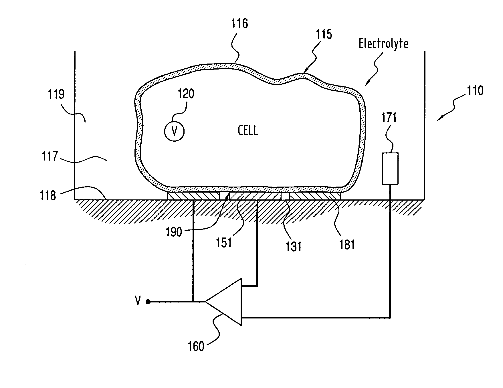
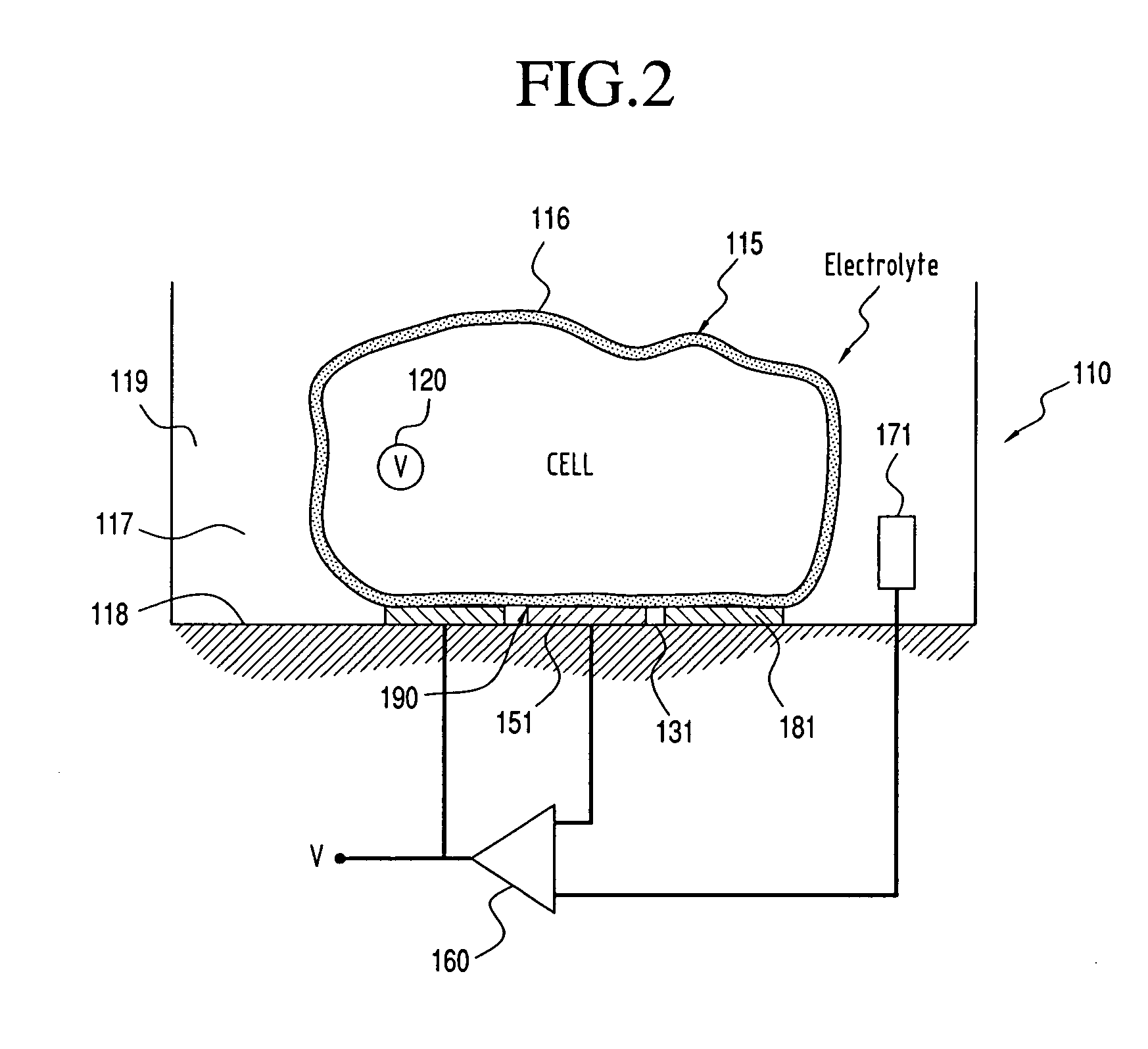
[0010]The feedback electrode is formed in an annular shape and substantially surrounds the sense electrode thus creating an annular fluid region therebetween. The amplifier has an input impedance and the coupling of the sense electrode to the object has an impedance. The amplifier has a gain set to compensate for an impedance dividing effect of the amplifier's input impedance and the impedance of the coupling to the sensing electrode, as well as to compensate for the drop in voltage from the feedback electrode to the electrolyte solution surrounding it. The value of the voltage in the annular region is set to be substantially equal to the value of the voltage in the object, while the impedance between the object and a stray voltage source is maximized. The value of the impedance between the sensing electrode and the feedback electrode is set by the physical spacing between them.
[0011]In use, the noise present while measuring an electric potential of a biological cell located in a nutrient bath may be reduced by sensing the electrical potential through an object with a sense electrode and maximizing the impedance between the object and any other source of voltage by using the feedback electrode to set the voltage of the electrolyte in the annular space substantially equal to the voltage of the object. Such a method improves the measurement of the electrical potential of a biological system by making the measurements less sensitive to stray coupling or electrical shunts to other elements in the system.

Problems solved by technology

The measurement of the electrical potential of an object, or region, in a conducting medium can be difficult when the element that senses the potential couples to the object with an electrical impedance that is comparable to or higher than other impedances coupled to the object.
Accurate measurements of electric potentials in fluid environments are made difficult by the conductivity of the fluid.
Traditionally, these patch clamp methods have been accomplished by individuals using very labor intensive techniques that permit only one cell to be measured at a time.
These techniques have met with limited success because the basic requirement of membrane penetration (or permeation) remains.
While Fromherz's work shows that the basic concept of capacitively based assessment of internal cell potential is feasible, his measurements of the intermediate layer are unreliable and complicated by stray electrical coupling to other elements in the overall system.
Therefore, the technique cannot be used to reliably infer the internal potential of a cell.
This severely limits practical implementation of Fromherz's technique or of any method relying on only a sensing electrode.

Method used


Image

  • System for Measuring the Electric Potential of a  Voltage Source
  • System for Measuring the Electric Potential of a  Voltage Source
  • System for Measuring the Electric Potential of a  Voltage Source

Examples


Embodiment Construction

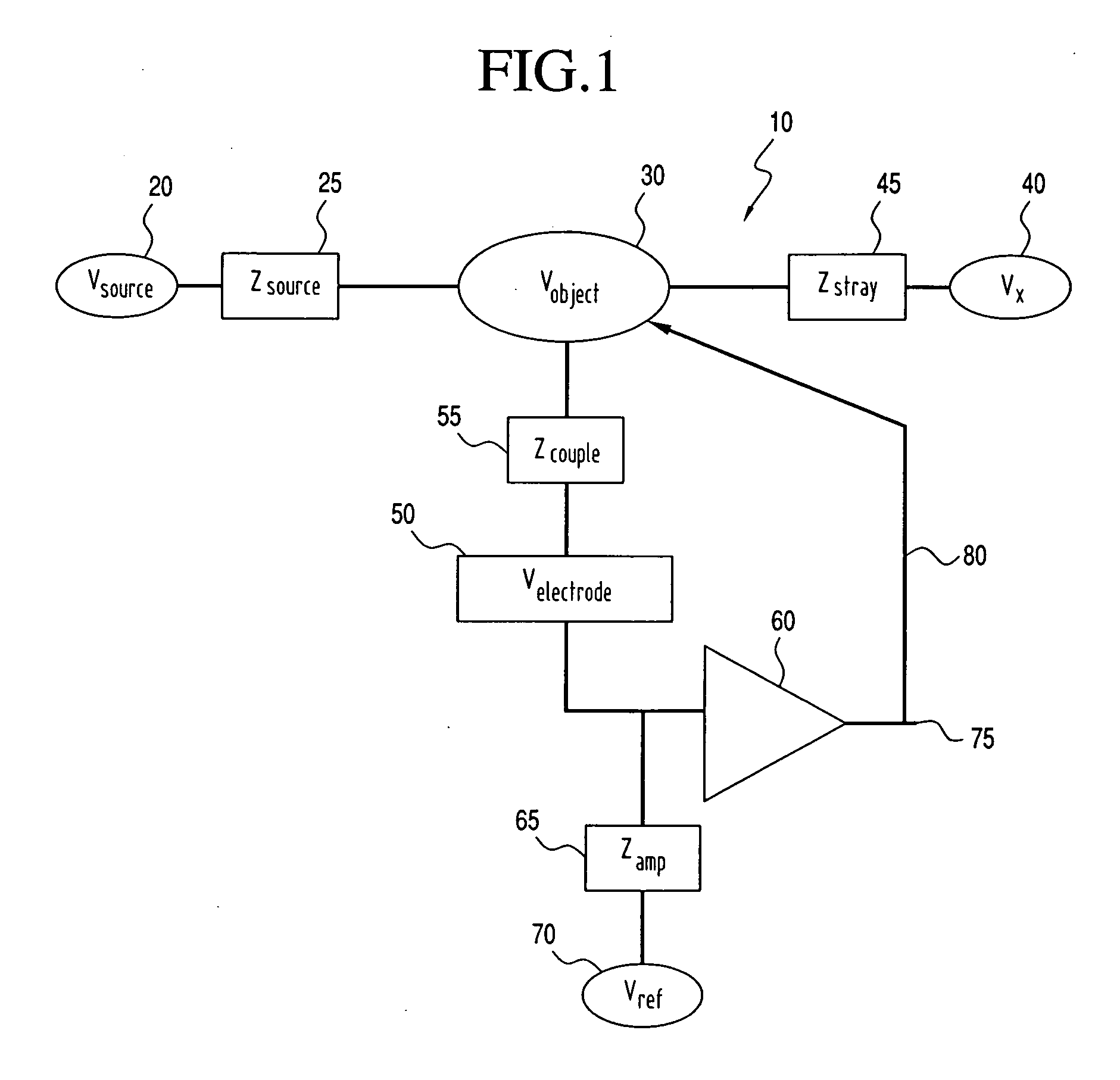
[0020]With initial reference to FIG. 1, the basic elements of the measurement problems to be addressed according to the invention is schematically shown at 10. A voltage source 20 producing voltage having a value Vsource is shown with an associated impedance 25 having a value Zsource. An object 30 has a voltage Vobject due to coupling to source 20. The “object” means a region of approximately equal electric potential, the boundaries of which are set by the physical configuration of the measurement problem. Object 30 could be a charged body, or could be a body of material held at a voltage via capacitive coupling to a local potential. In one case, where the ultimate goal is to measure Vsource, one may be constrained by the physical aspects of the problem to measuring the voltage Vobject of object 30. For example, one may desire to measure the internal potential of a cell via an external electrode as in the work of

[0021]Fromherz et al., and object 30 could be the boundary layer of pro...


PUM


Abstract

A non-invasive measurement system (110) for measuring the electrical potential of a voltage source (20, 120) includes a sensing electrode (50, 151) spaced from the voltage source (20, 120). Preferably the voltage source (20, 120) is within a biological cell (115) located in a nutrient bath (119) including electrolytic medium (117) and an object (30, 190) is a portion of the electrolytic fluid (117) located between the cell (115) and the sensing electrode (50, 151). A feedback electrode (181) is formed in an annular shape and surrounds the sensing electrode (50, 151) thus creating an annular fluid region therebetween. The value of the voltage in the annular region (131) is set substantially equal to the value of the voltage in the object (190) and therefore the impedance between the object (190) and a stray voltage source (40) is maximized.

Description

BACKGROUND OF THE INVENTION[0001]1. Field of the Invention[0002]The present invention pertains to the art of electrical sensing devices and, more particularly, to a system having a high electrical impedance that measures the electrical potential of a voltage source.[0003]2. Discussion of the Prior Art[0004]The measurement of the electrical potential of an object, or region, in a conducting medium can be difficult when the element that senses the potential couples to the object with an electrical impedance that is comparable to or higher than other impedances coupled to the object. This situation arises when the sensing is predominantly capacitive and in cases when the sensing element is very small. For example, such situations arise in electrophysiology measurements used in biological research, sensing in a fluid medium, and the control of voltages in processes that involve a conducting fluid or medium.[0005]Accurate measurements of electric potentials in fluid environments are made...

Claims


Application Information

Patent Timeline
IPC IPC(8): G01N27/02G01R19/00
CPCG01N33/5438G01N33/48728
Inventor HIBBS, ANDREW D.KRUPKA, MICHEAL ANDREWMATTHEWS, ROBERTKUNSTMANAS, LINAS
Owner ELECTRONICS BIOSCI
Learn More