Eureka AIR delivers breakthrough ideas for toughest innovation challenges, trusted by R&D personnel around the world.

Transflective liquid crystal display

Inactive Publication Date: 2010-06-17
SONY ERICSSON MOBILE COMM AB
View PDF5 Cites 19 Cited by
  • Summary
  • Abstract
  • Description
  • Claims
  • Application Information

AI Technical Summary

Benefits of technology

[0009]The advantage of using a reflective layer with adjustable reflectivity is the ability to achieve high reflectivity in good lighting conditions and low reflectivity (or high transmissivity) of the display when the display is used in low light conditions. In this fashion valuable battery time consumed by the backlight system may be saved in good lighting conditions sacrificing very little of the readability of the display. On the other hand, good readability of the display is also achieved in low lighting conditions.
[0012]In a further embodiment, the display according to the present invention may comprise a light sensor which may detect the ambient light level impinging onto the display, such that the first control signal is dependent on the detected ambient light level. In this way, the reflectivity of the display may be automatically adjusted.
[0022]In a further embodiment the portable electronic device may comprise a processing unit adapted to compare the amount of ambient light detected by the light sensor with one or more threshold values and to instruct the control unit to transmit a first control signal to the reflective layer. Also, the processing unit may be further adapted to instruct the control unit to transmit a second control signal to the illumination system depending on the first control signal. In this fashion a first control signal altering the reflectivity of the reflective layer in the display may lead to altering of the light intensity produced by the backlight system of the display, such that higher reflectivity values lead to lower light intensity values for the backlight system.

Problems solved by technology

Mainly the power consumption of FDP displays stems from their backlight function used in order to illumine the display when it is used in unfavourable lighting conditions.
In recent years, electronic devices with displays using so called OLED (Organic Light Emitting Display) have appeared on the market eliminating the need of a backlight function and, under special circumstances, possibly also the power consumption of such a display.
However, the cost of OLED displays is till higher than that of LCD displays with backlight and at the same time OLED displays may show signs of colour shifting with time.

Method used


Image

  • Transflective liquid crystal display
  • Transflective liquid crystal display
  • Transflective liquid crystal display

Examples


Embodiment Construction

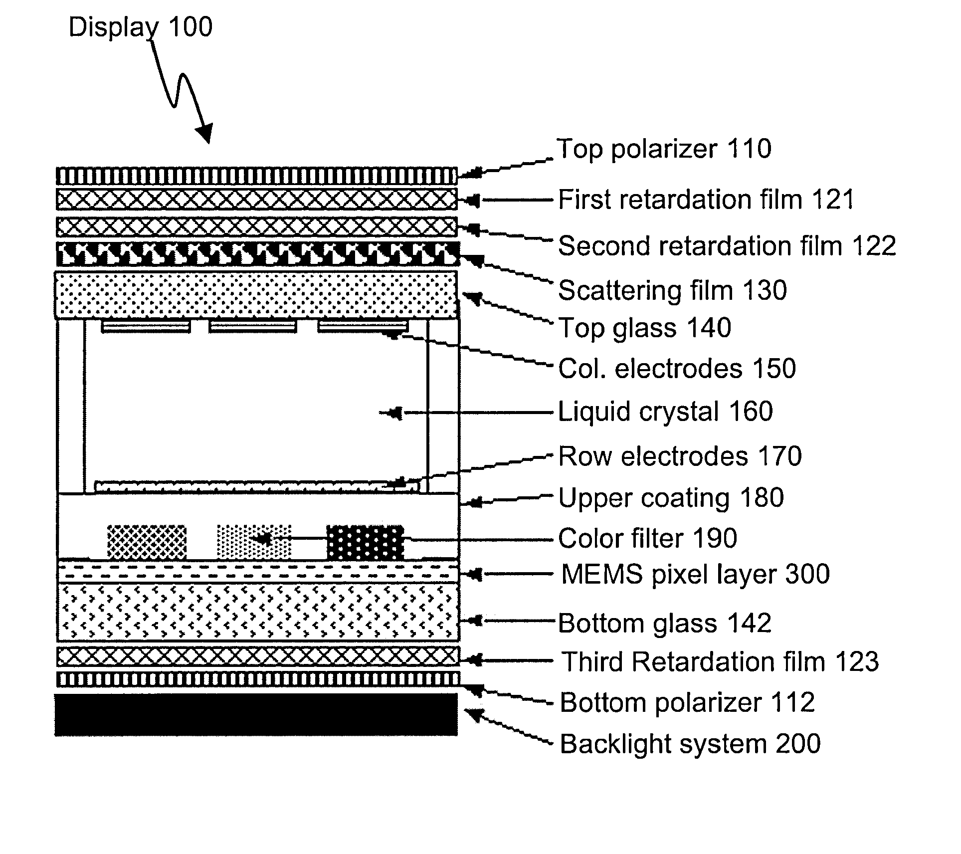
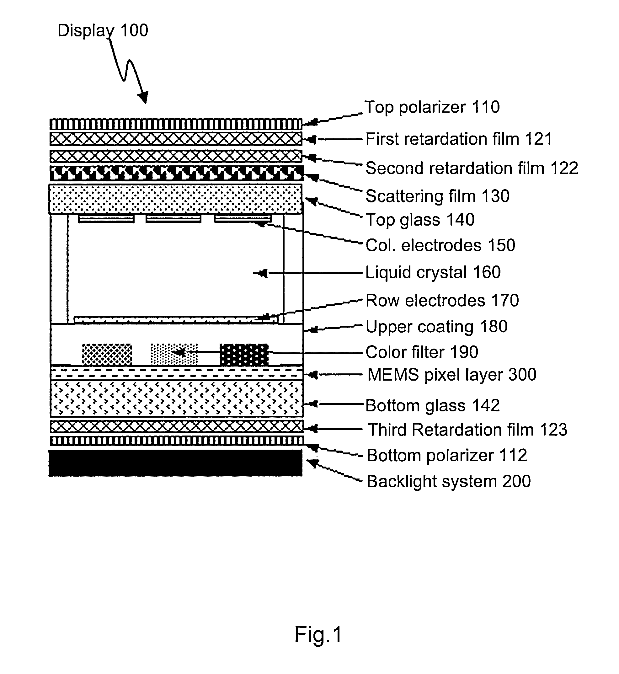
[0032]FIG. 1 illustrates a display 100 comprising a MEMS (Microelectromechanical Systems) pixel layer according to one embodiment of the present invention. The example embodiment shown in FIG. 1 is related to a standard LCD display used in a portable electronic device. However, it should be mentioned that the use of the present invention in connection with an LCD display is only exemplary and should not be conceived as limited to exclusively this application. In fact, present invention may be used together with any other display technology having a backlight function and which uses control signals to project an image onto a display surface

[0033]Therefore, the present invention may be used with displays using LCD, PDP and other technologies using a backlight system to illumine the display.

[0034]As seen from FIG. 1, the display according to the present invention comprises a number of layers stacked on top of each other. It should be mentioned that the display in the figure is not draw...


PUM


Abstract

The present invention describes a display comprising a liquid crystal layer, an illumination system and a reflective layer, where the reflective layer is arranged below the liquid crystal layer, where the reflectivity of the layer is adjustable. In this way the amount of ambient light passing through the display and being reflected by the reflective layer can be altered. Moreover, the present invention describes a method and computer program for controlling reflectivity of a flat display panel in a portable electronic device.

Description

TECHNICAL FIELD[0001]The present invention is related to displays for portable electronic devices. More specifically it is related to transflective (partly reflective and partly transmissive) liquid crystal displays used in these devices.BACKGROUND ART[0002]Electronic devices with FDP (Flat Panel Displays) based on different technologies, such as PDP (Plasma Display Panel) and LCD (Liquid Crystal Display) have existed for a number of years on the market now. While offering superior sharpness and level of detail compared to previously existing cathode ray tubes there is a constant need to reduce their power consumption in portable electronic devices. Mainly the power consumption of FDP displays stems from their backlight function used in order to illumine the display when it is used in unfavourable lighting conditions.[0003]In recent years, electronic devices with displays using so called OLED (Organic Light Emitting Display) have appeared on the market eliminating the need of a back...

Claims


Application Information

Patent Timeline
IPC IPC(8): G02F1/1335
CPCG02F1/133553G02F1/133555G02F2203/07G02F2203/62G09G3/20G09G2360/144G09G3/346G09G3/3611G09G2300/023G09G2300/0456G09G3/3406
Inventor HUNT, ALEXANDER
Owner SONY ERICSSON MOBILE COMM AB
Why Eureka
Eureka Blog
Learn More