
Optical Information Recording Medium, Method Of Manufacturing The Same, And Sputtering Target

Inactive Publication Date: 2010-06-17
PANASONIC CORP
View PDF16 Cites 8 Cited by
  • Summary
  • Abstract
  • Description
  • Claims
  • Application Information

AI Technical Summary

Benefits of technology

[0008]The present invention has been made in order to solve the above-mentioned problems, and is intended to provide a transmittance adjusting layer having a high film formation rate that is not dependent on the degree of vacuum in a film forming chamber while maintaining the good characteristics such as a refractive index and moisture resistance of conventional transmittance adjusting layers not to degrade significantly, and thus to provide an optical information recording medium having high mass productivity. The present invention also is intended to provide a sputtering target that can be used for forming a transmittance adjusting layer as described above.
[0012]The optical information recording medium of the present invention makes it possible to obtain a transmittance adjusting layer having a high film formation rate that is not dependent on the degree of vacuum in a film forming chamber without degrading its characteristics, and therefore to provide an optical information recording medium that includes an information layer having a high transmittance and is suitable for mass production. Furthermore, the method of manufacturing an optical information recording medium of the present invention and the sputtering target of the present invention make it possible to manufacture the optical information recording medium of the present invention easily.

Problems solved by technology

In addition, a transmittance adjusting layer having a high refractive index needs to be disposed to increase the transmittance further by optical interference.
However, a TiO2 layer conventionally used as a transmittance adjusting layer has a problem in that when the TiO2 layer is formed by sputtering, which is a commonly known film forming method, the thickness of the film formed per unit time (hereinafter referred to as a “film formation rate”) is small and it takes a long time to obtain a desired thickness (that is, the film formation rate is low).
Therefore, the TiO2 layer has another problem in that it is difficult to maintain the thickness of the TiO2 layer within a desired thickness range particularly during mass production thereof.
Accordingly, the number of TiO2 layers serving as transmittance adjusting layers also increases, which may make this problem more serious.

Method used


Image

  • Optical Information Recording Medium, Method Of Manufacturing The Same, And Sputtering Target
  • Optical Information Recording Medium, Method Of Manufacturing The Same, And Sputtering Target
  • Optical Information Recording Medium, Method Of Manufacturing The Same, And Sputtering Target

Examples


embodiment 1

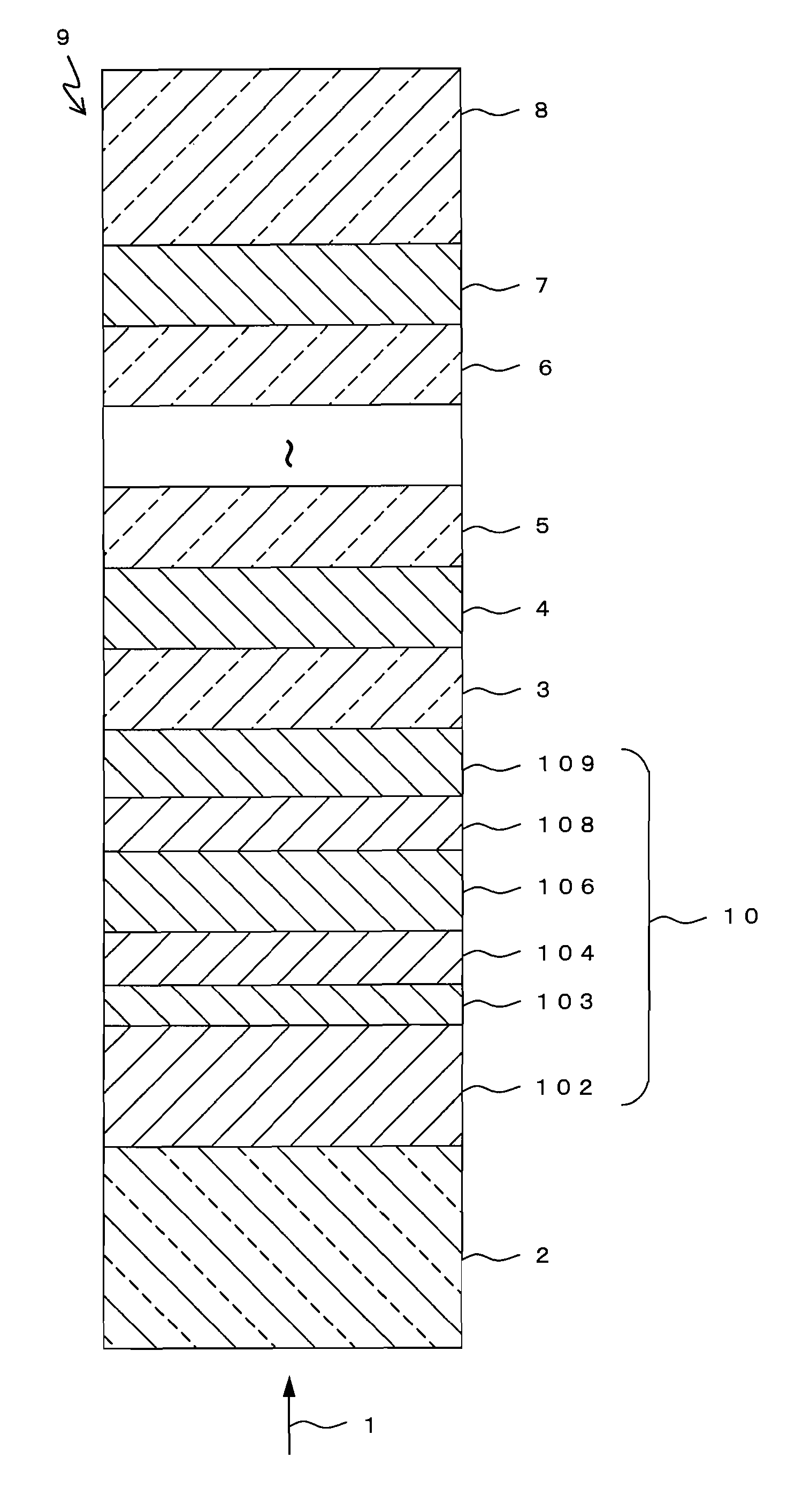
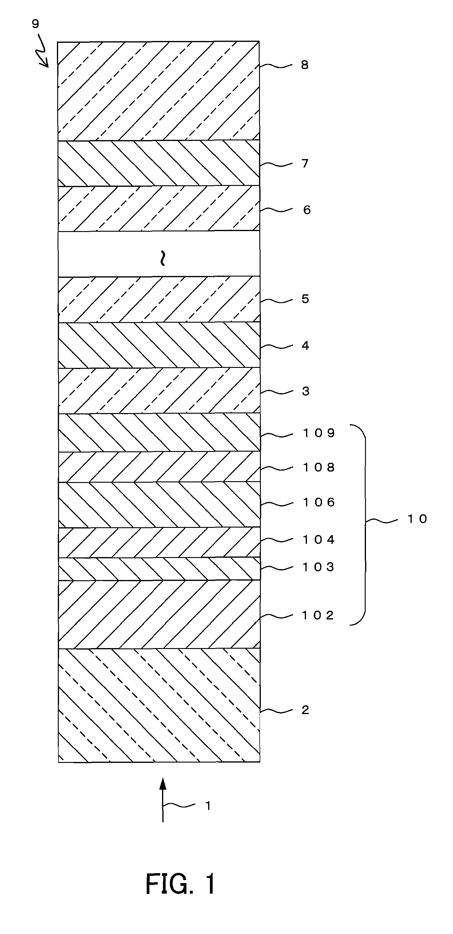
[0048]In Embodiment 1, an example of an optical information recording medium of the present invention will be described. FIG. 1 shows a partial cross-sectional view of an optical information recording medium 9 according to Embodiment 1. The optical information recording medium 9 is a multi-layer optical information recording medium on / from which information can be recorded / reproduced by a laser beam 1 irradiated from one side of the medium.

[0049]The optical information recording medium 9 includes a substrate 8, and N (N is a natural number that satisfies N≧2) information layers including an N-th information layer 7, . . . , a second information layer 4, and a first information layer 10 that are formed sequentially on the substrate 8, with respective intermediate layers 6, 5, 3, etc. being interposed therebetween, and a transparent layer 2. In the present embodiment, an information layer disposed at the K-th position (1≦K≦N) when counted from the incident side of the laser beam 1 is ...

embodiment 2

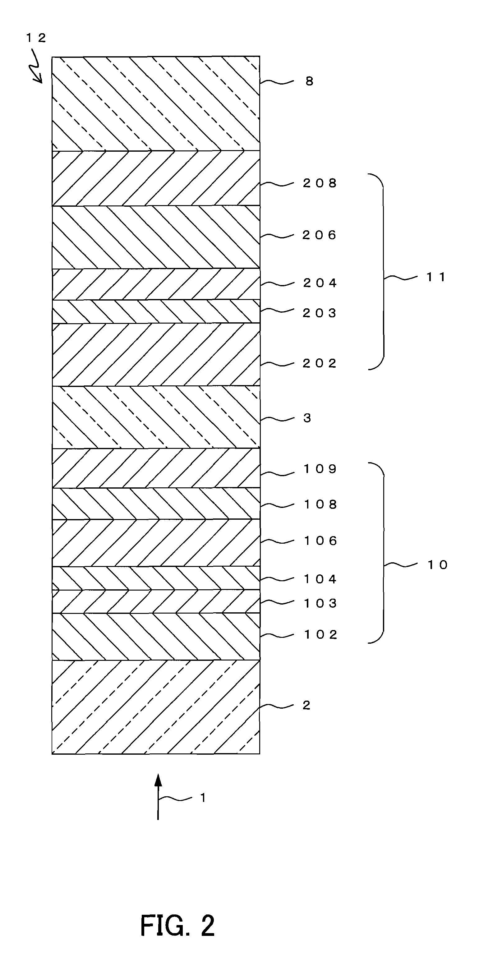
[0115]In Embodiment 2, an example of an optical information recording medium will be described, in which the multi-layer optical information recording medium according to Embodiment 1 of the present invention is provided with two information layers, that is, N=2. FIG. 2 shows a partial cross-sectional view of an optical information recording medium 12 according to Embodiment 2. The optical information recording medium 12 is a two-layer optical information recording medium on / from which information can be recorded / reproduced by a laser beam 1 irradiated from one side of the medium.

[0116]The optical information recording medium 12 includes a substrate 8, and a second information layer 11, an intermediate layer 3, a first information layer 10, and a transparent layer 2 that are formed sequentially on the substrate 8. The substrate 8, the intermediate layer 3, the first information layer 10, and the transparent layer 2 can be formed of the same materials as those of the corresponding la...

embodiment 3

[0146]In Embodiment 3, an example of an optical information recording medium will be described, in which the multi-layer optical information recording medium according to Embodiment 1 is provided with three information layers, that is, N=3. FIG. 3 shows a partial cross-sectional view of an optical information recording medium 16 according to Embodiment 3. The optical information recording medium 16 is a three-layer optical information recording medium on / from which information can be recorded / reproduced by a laser beam 1 irradiated from one side of the medium.

[0147]The optical information recording medium 16 includes a substrate 8, and a third information layer 15, an intermediate layer 5, a second information layer 14, an intermediate layer 3, a first information layer 13, and a transparent layer 2 that are formed sequentially on the substrate 8. The substrate 8, the intermediate layers 3 and 5, and the transparent layer 2 can be formed of the same materials as those of the corresp...


PUM

PropertyMeasurementUnit
Thicknessaaaaaaaaaa
Thicknessaaaaaaaaaa
Volumeaaaaaaaaaa

Abstract

An optical information recording medium (9) of the present invention is an optical information recording medium including: N information layers, where N is a natural number of 2 or more; and an intermediate layer for separating the N information layers optically from each other. With the N information layers being referred to as a first information layer (10) to an N-th information layer (7) sequentially from an optical beam incident side, a first information layer (10) corresponding to an L-th information layer included in the N information layers includes a recording layer (104) on which information can be recorded by irradiation with an optical beam, a reflective layer (108), and a transmittance adjusting layer (109) in this order from the optical beam incident side, where L is an at least one natural number that satisfies 1≦L≦N−1. The transmittance adjusting layer (109) contains tungsten (W) and oxygen (O).

Description

TECHNICAL FIELD[0001]The present invention relates to an information recording medium for recording, erasing, rewriting and / or reproducing information optically, a method of manufacturing the same, and a sputtering target.BACKGROUND ART[0002]One type of conventional information recording medium is a phase-change type information recording medium that utilizes a phenomenon in which a recording layer (phase-change material layer) included in the medium undergoes a phase change. Among the phase-change type information recording media, there is a type of information recording medium that utilizes a laser beam to record, erase, rewrite or reproduce information optically. This type of information recording medium has a recording layer made of a phase change material that changes its state between, for example, a crystalline phase and an amorphous phase by heat generated by irradiation with a laser beam. A difference in reflectance between the crystalline phase and the amorphous phase is d...

Claims


Application Information

Patent Timeline
IPC IPC(8): G11B7/241B32B3/02G11B7/24C23C14/34G11B7/24035G11B7/24038G11B7/24062G11B7/243G11B7/2433G11B7/2437G11B7/254G11B7/257G11B7/258G11B7/259
CPCC23C14/08Y10T428/21G11B7/24038G11B7/252G11B7/259G11B7/266G11B2007/2431G11B2007/24312G11B2007/24314G11B2007/24316G11B2007/25706G11B2007/25708G11B2007/2571G11B2007/25715C23C14/3414
Inventor NISHIHARA, TAKASHIKOJIMA, RIEKUSADA, HIDEOYAMADA, NOBORU
Owner PANASONIC CORP
Learn More