
Processes for dispersing substances and preparing composite materials

a technology of dispersing substances and composite materials, applied in the field of dispersing substances and preparing composite materials, can solve the problems of reducing productivity, increasing throughput time, and forming larger particles, and achieves stable dispersions, improved mixing, and high dispersion stability

Inactive Publication Date: 2010-06-17
MINUSNINE TECH
View PDF1 Cites 41 Cited by
  • Summary
  • Abstract
  • Description
  • Claims
  • Application Information

AI Technical Summary

Benefits of technology

The present invention provides processes for manufacturing composite materials and fluids by dispersing particles in a viscous medium. The processes allow for easy mass production of stable dispersions with little or no sediment and require little or no surfactant, compatibilizing agent, or other potentially contaminating agent. The invention also provides methods for dispersing particles in a polymeric fluid, resulting in a one-phase mixture with improved mixing and smaller domains. The invention has various applications, such as in the manufacturing of optical components, sensors, and electronics.

Problems solved by technology

The roller mill method uses compressive forces to crush fine grained powder to smaller particle sizes, while at the same time absorbing resin components such as a compatibilizing agents are compressed into the surface of the particle by a high shearing mixing force, but non-uniform mixed portions are also compressed by this strong force causing the formation of larger (agglomerated) particles.
This not only prevents crushing of these smaller particles but also increases throughput time consequently reducing productivity.
Roller mills also often are acoustically polluting, cause low frequency vibrations, and are labor intensive.
Such processes undesirably form sediment when fine grained powder having an average primary particle size in nanometer to micron scales are dispersed into a low viscosity solvent or resin.
Jet mill dispersion methods are known to cause collisions of liquids at high pressure, which requires large, dangerous, and expensive equipment.
The drawbacks of these methods are similar to the homogenizing high speed mixing systems.
This dispersion system also has drawbacks in terms of cleaning and maintenance do to complicated internal mechanisms.
Jet mills also often are large, expensive, and changing compositions or cleaning are very labor intensive.
However, particle crushing occurs during the process, which can give rise to agglomeration of particles and increase liquid viscosity, which reduces productivity.
Dispersions made by the bead mill dispersion method are also limited by the relatively large size of commercially available beads and the interstitial space between the crushing beads (determined by bead diameter.
Thus, it is difficult to disperse powder having an average primary particle size in micron to nanometer scales or less into a solvent or a solution, and to construct a dispersion system that provides high volume production.
The beads themselves are often very difficult to clean since the particle used can be highly compressed into the surface structures of the bead themselves.
Cleaning often requires extensive flushing with water or solvent, which is expensive, potentially polluting, and highly labor intensive.
Ultrasonic batch type dispersers generally have liquid circulation problems, and as a result, ultrasound is not uniformly applied to liquid dispersions.
Ultrasonic dispersers may also damage delicate materials.
Various problems, such as those described above, become more pronounced as the particle size of the fine grained powder becomes smaller.
Moreover, dissolved particles generally cannot be dispersed by any of the previously mentioned methods.
The aforementioned techniques also suffer from particle agglomeration problems.
Because the surface area / volume ratio of fine grained powders increases with decreasing particle size, there is an increased tendency for particles to agglomerate, which is generally undesirable.
Reducing the size of these so-called “secondary agglomerated particles” is difficult for commercial powder producers.

Method used


Image

  • Processes for dispersing substances and preparing composite materials
  • Processes for dispersing substances and preparing composite materials
  • Processes for dispersing substances and preparing composite materials

Examples


embodiment featuring minimal

Agitation with Larger aqueous phase

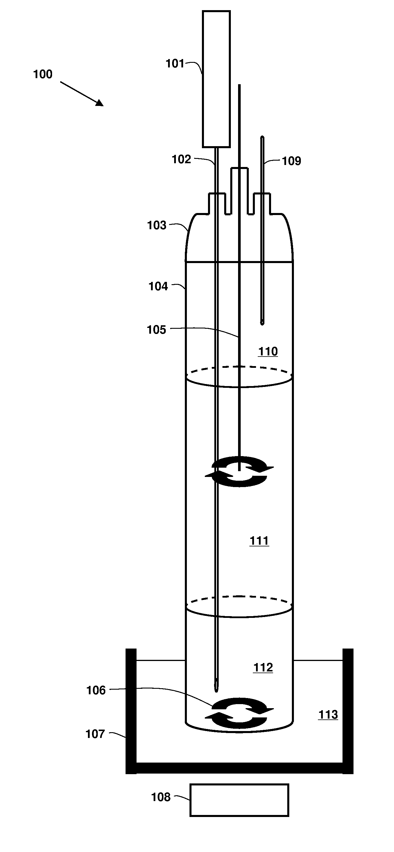
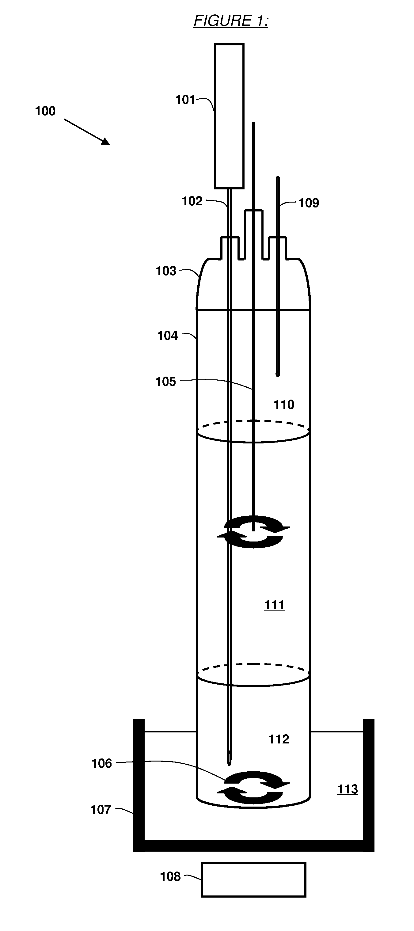
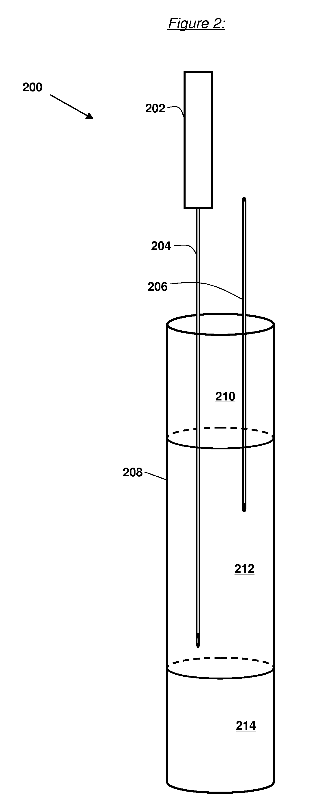
[0102]FIG. 6 provides an embodiment for a system 600 which represents a variation of system 100 and 200. System 600 can be comprised of a resin kettle 602 containing an inert gas phase 604, a continuous aqueous phase 606 and phase 608. System 600 contains a larger aqueous phase 608 as compared to the aqueous phases 111 and 212.

[0103]Multiple Phase Systems and Complex Stirring Geometries. FIGS. 5-8 illustrate systems with more than two phases or complex stiffing regimes.

[0104]Multiple phase systems. The invention need not be constrained to only two phases. FIG. 6 shows a possible three-phase system. The three phases are immiscible in each other. Components in the middle phase which are soluble in either the upper or lower phase can be extracted out. Another example would comprise an upper phase of aliphatic epoxy resin with a density lower than water, a middle phase of water, and a lower phase of epoxy resin with a density greater than water. Soluti...

embodiment featuring smaller

Resin Kettle Diameter

[0106]FIG. 7 provides an embodiment for a system 700 which represents a variation of system 100 and 200. System 700 can be comprised of a resin kettle 702 containing an inert gas phase 704, a continuous aqueous phase 706 and phase 708. The resin kettle 702 of system 700 can be narrower in diameter as compare to the resin kettles 104 and 208 which results in a smaller interface between the aqueous phase 706 and phase 708.

[0107]Suitable Apparatus for the Fabrication of Continuous Thread or Wire. FIG. 15 shows an apparatus configuration for the fabrication of long rod structures as would be useful in the manufacture of thread or wire.

Embodiment Featuring Larger Resin Kettle Diameter

[0108]FIG. 8 provides an embodiment for a system 800 which represents a variation of system 100 and 200. System 800 can be comprised of a resin kettle 802 containing an inert gas phase 804, a continuous aqueous phase 806 and phase 808. The resin kettle 802 of system 800 can be wider in d...

embodiment featuring

Larger aqueous phase with Minimal Interface

[0110]FIG. 10 provides an embodiment for a system 1000 which represents a variation of system 100 and 200. System 1000 can be comprised of a resin kettle 1002 containing an inert gas phase 1006 and a continuous aqueous phase 1008 and connected on the bottom to resin kettle 1004 which contains phase 1010.

Embodiment for a Continuous Process

[0111]FIG. 11 illustrates an embodiment of a continuous system 1100 which represents a variation of system 100 and 200. System 1100 includes conduits 1102, 1104, 1110, 1114, 1124, 1128, 1136 and 1140; resin kettles 1106, 1116, 1130 and 1143; and valves 1112, 1126 and 1138. Conduit 1102 provides an solution drip into resin kettle 1106. Conduit 1104 provides a solvent drip in resin kettle 1102. Resin kettle includes an phase 1108 (e.g., comprising a mixture of epoxy and solvent). Suitable solvents can be an compound, a particularly preferred solvent being dimethyl formamide (DMF). The phase 1108 drains into c...


PUM

PropertyMeasurementUnit
frequencyaaaaaaaaaa
diameteraaaaaaaaaa
volumeaaaaaaaaaa

Abstract

Disclosed herein are processes for dispersing a plurality of unaggregated particles, such as nanoparticles and microparticles, in a viscous medium. The dispersions can be used for making a variety of useful materials, such as carbon nanotube composites.

Description

CROSS REFERENCE TO RELATED APPLICATIONS[0001]This patent application claims the benefit of U.S. Provisional Patent Application No. 60 / 830,385, filed Jul. 12, 2006, the entirety of which is incorporated by reference herein.FIELD OF THE INVENTION[0002]The disclosed invention is in the field of processes for preparing dispersions of substances in liquid mediums. The disclosed invention is also in the field of preparing composite materials, particularly nanocomposite materials. The disclosed invention is also in the field of processing materials comprising carbon nanotubes.BACKGROUND TO THE INVENTION[0003]Dispersing fine grained powder having an average primary particle size of micron to nanometer scales or smaller into a solvent, resin, or polymer has become increasingly important in producing a variety of useful materials, such as functional films, adhesives, coatings, bulk materials, and the like. In particular, dispersing fine-grained powder is important in terms of forming uniforml...

Claims


Application Information

Patent Timeline
Patent Type & Authority Applications(United States)
IPC IPC(8): C08J3/11B01J13/00
CPCC08J3/2053C08L21/00C08K3/0033C08K3/013
Inventor KURZ, DAVID W.
Owner MINUSNINE TECH
Learn More