
Processing sensed accelerometer data for determination of bone healing

a technology of accelerometer and data acquisition, which is applied in the field of orthopaedic implants, can solve the problems of insufficient information for physicians to adequately assess the progress of healing, inability to quantify the load sharing between implants and bone during fracture healing from standard radiographs, ct, or mri, and achieves accurate and stable connection, promote/accelerate bone healing or a revision surgery. , the effect of promoting/accelerating bone healing

Active Publication Date: 2010-06-17
SMITH & NEPHEW INC
View PDF102 Cites 65 Cited by
  • Summary
  • Abstract
  • Description
  • Claims
  • Application Information

AI Technical Summary

Benefits of technology

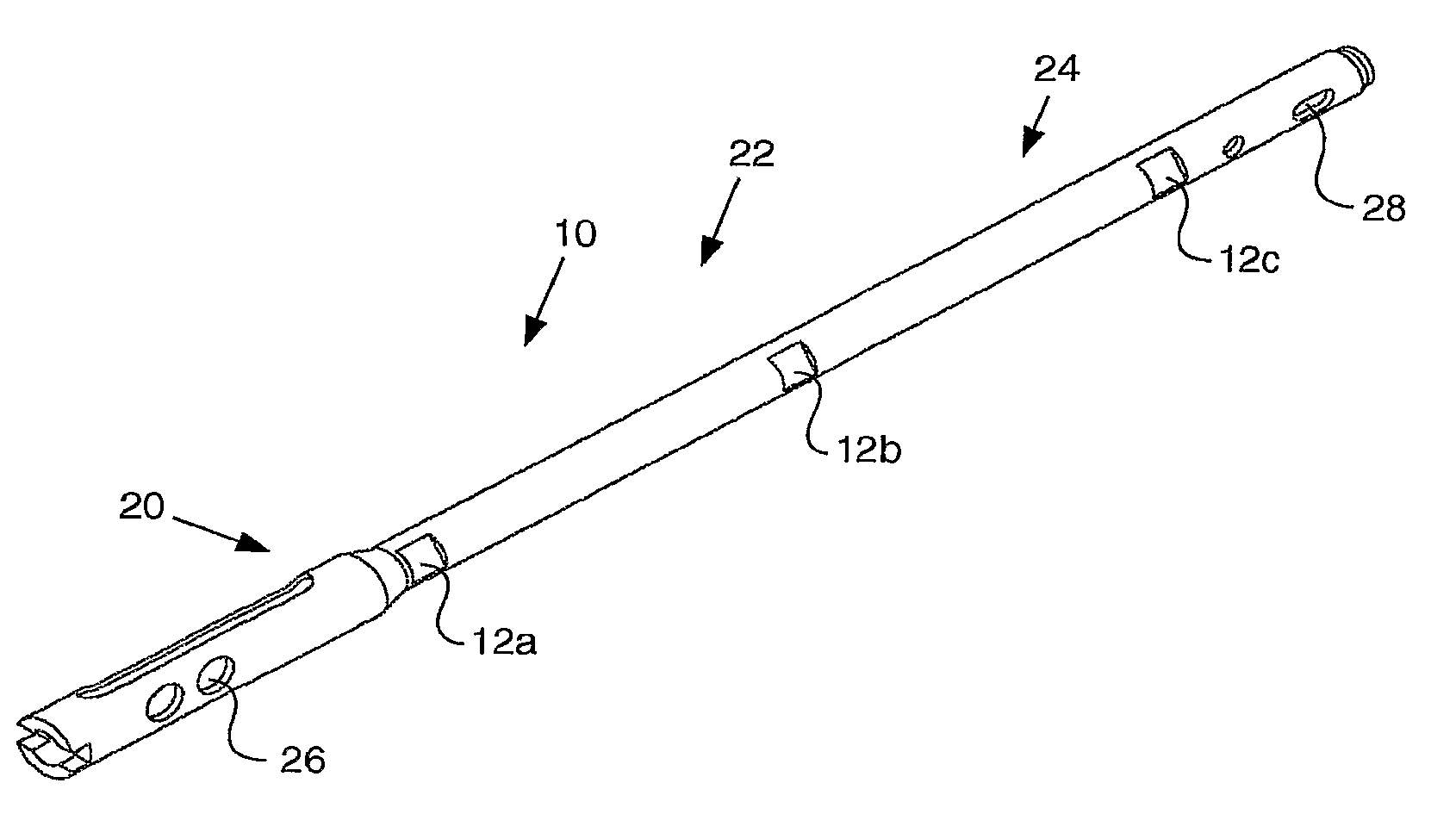
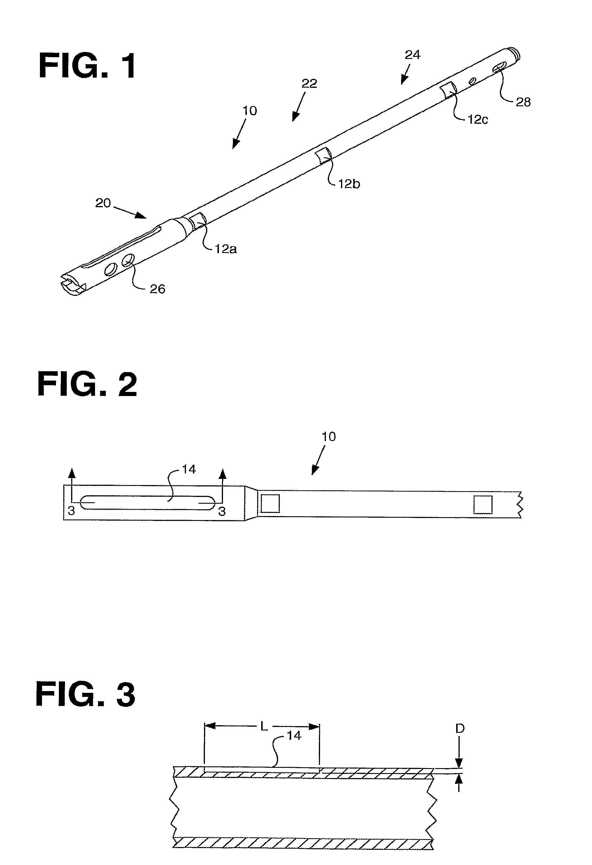
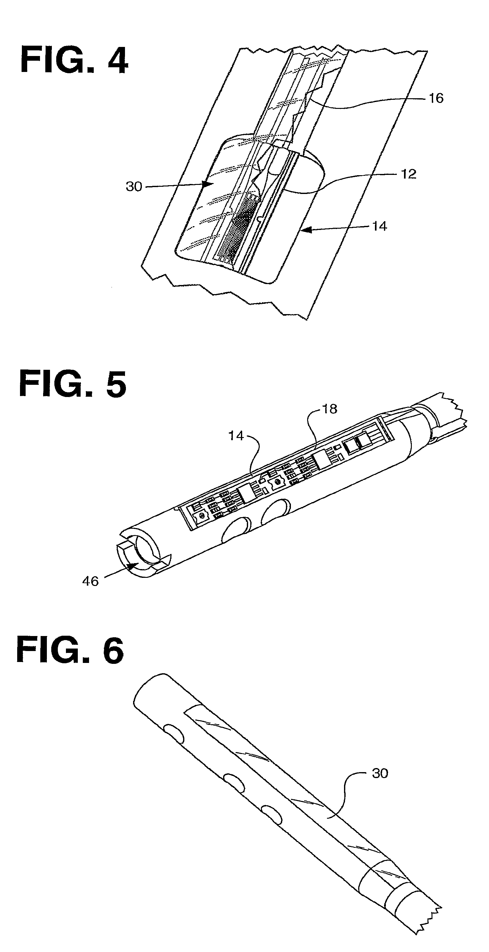
[0030]The advantage of the invention over the prior art concerns the incorporation of the components within the smart implant in a manner that protects the components, provides an accurate and stable connection between the sensor and its environment, maintains the functionality of the implant itself, and is suitable for large scale manufacture. The device allows for information to be gathered and processed yielding useful clinical data with respect to a patient's bone healing cascade.
[0031]The instrumented device removes the estimation from the conventional diagnostic techniques such as x-ray, CT and MRI imaging by providing the patient objective quantitative data collected from them through the healing process. Currently, there is no device which utilizes accelerometer data to monitor fracture healing. The device described within addresses this by having on board sensors and a memory facility enabling patient data to be stored thus allowing for early transmission of data. This data includes patient history and patient activity. The device also enables early intervention by the surgeon, if required, such as administration of drugs, injection of orthobiologics, cements or demineralized bone matrix to help promote / accelerate bone healing or a revision surgery.
[0032]There a number of other potential clinical benefits including reduced number of clinic visits, reduced pain suffered by the patient, improved data on fracture healing, and early notification of delayed or non-union.

Problems solved by technology

Current methods of assessing the healing process, e.g. radiography, patient testimonial, etc., do not provide physicians with sufficient information to adequately assess the progress of healing, particularly in the early stages of healing.
X-ray images can only show callus geometry and cannot be used to assess the mechanical properties of the consolidating bone.
Therefore, it is difficult to quantify the load sharing between implant and bone during fracture healing from standard radiographs, CT, or MRI scans.
Unfortunately, there is no in vivo data available quantifying the skeletal loads encountered during fracture healing as well as during different patient and physiotherapy activities.

Method used


Image

  • Processing sensed accelerometer data for determination of bone healing
  • Processing sensed accelerometer data for determination of bone healing
  • Processing sensed accelerometer data for determination of bone healing

Examples


first embodiment

[0196]The invention includes a method for determining the healing progression status of a subject. The method includes the steps of: (a) collecting accelerometer data through use of an accelerometer operatively connected to the subject; (b) retrieving the collected accelerometer data, the accelerometer data having a time domain component; (c) transforming the time domain accelerometer data into frequency domain accelerometer data; and (d) analyzing the frequency domain accelerometer data for healing progression of the subject. Optional steps may include wirelessly conveying accelerometer data to a remote processing system and communicating the analysis of the data to a user. In general, the accelerometer data is taken while the subject is undergoing a predefined task. For example, the predefined task may be ambulation. The predefined task may be performed preoperatively, intraoperatively, or postoperatively. For the intraoperative step, the subject may be assisted by a surgeon or ot...

second embodiment

[0197]The invention includes a second embodiment for determining the healing progression status of a subject. The method includes the steps of: (a) attaching an accelerometer to a subject; (b) collecting accelerometer data through use of the accelerometer; and (c) analyzing the accelerometer data to determine if the subject has progressed in healing status. The step of attaching an accelerometer to a subject includes installing a smart implant in the subject. As examples, the smart implant may be a bone plate, a bone screw, a bone peg, a bone staple, an intramedullary nail, an intramedullary nail cap, an intramedullary nail / plate, an interference screw, a hip replacement stem, a hip replacement femoral neck, a hip replacement femoral head, a hip replacement acetabular liner, a hip replacement acetabular shell, a knee replacement tibial tray, a knee replacement tibial tray liner, a knee replacement femoral component, a knee replacement tibial tray shaft extension, a knee replacement ...


PUM


Abstract

A system (800) for processing accelerometer data is disclosed. The system (800) includes an accelerometer (806), a first processor (810), a power supply (816), and a second processor (804). The accelerometer (806) measures a physiological acceleration parameter. The first processor (810) is operatively connected to the accelerometer (806). The first processor (810) is configured to receive the acceleration parameter from the accelerometer (806) and configured to output machine readable acceleration data. The machine readable acceleration data includes time domain accelerometer data. The power supply (816) is electrically connected to the first processor (810). The second processor (804) is configured to receive the machine readable acceleration data and transform the time domain accelerometer data into frequency domain accelerometer data. The frequency domain accelerometer data may be used to estimate patient healing status.

Description

CROSS-REFERENCE TO RELATED APPLICATIONS[0001]N / ASTATEMENT REGARDING FEDERALLY SPONSORED RESEARCH OR DEVELOPMENT[0002]Not Applicable.APPENDIX[0003]Not Applicable.BACKGROUND OF THE INVENTION[0004]1. Field of the Invention[0005]This invention relates generally to orthopaedic implants and, more particularly, orthopaedic implants having data acquisition capabilities.[0006]2. Related Art[0007]The trauma fixation implants currently available on the market are passive devices because their primary function is to support the patient's weight with an appropriate amount of stability whilst the surrounding fractured bone heals. Current methods of assessing the healing process, e.g. radiography, patient testimonial, etc., do not provide physicians with sufficient information to adequately assess the progress of healing, particularly in the early stages of healing. X-ray images can only show callus geometry and cannot be used to assess the mechanical properties of the consolidating bone. Therefor...

Claims


Application Information

Patent Timeline
Patent Type & Authority Applications(United States)
IPC IPC(8): A61B5/11G08B21/00
CPCA61B5/0031A61B5/1038A61B5/11A61B2562/0219A61B5/4504A61B5/6807A61B5/7257A61B5/412
Inventor JANNA, SIED W.WILSON, DARREN JAMESBRADY, PETER A.
Owner SMITH & NEPHEW INC
Learn More