
Vehicle, control method of vehicle, and driving apparatus

Inactive Publication Date: 2010-06-17
TOYOTA JIDOSHA KK +1
View PDF17 Cites 35 Cited by
  • Summary
  • Abstract
  • Description
  • Claims
  • Application Information

AI Technical Summary

Benefits of technology

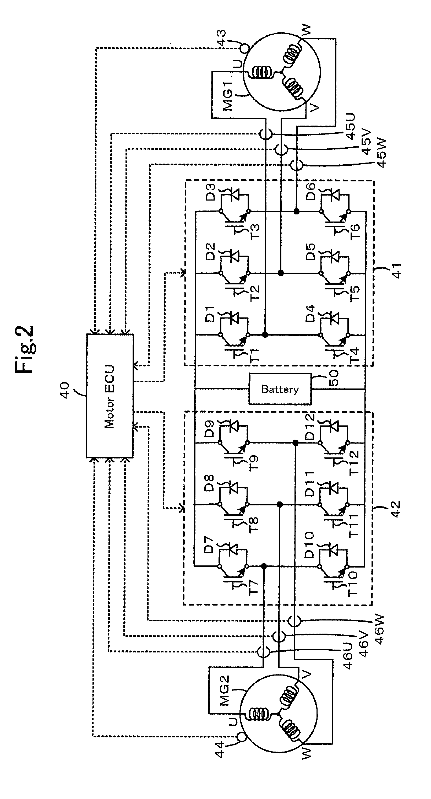
[0008]In one preferable application of the vehicle of the invention, the preset switching state may be a switching state that closed circuits are formed in all phases of the second inverter circuit. This arrangement enables to reduce the braking force applied to the vehicle from the counter electromotive force generated by rotation of the motor.
[0009]In another preferable application of the vehicle of the invention, the controller may be configured to control the internal combustion engine and the first inverter circuit using the cancellation driving force that is obtained from a rotation speed-driving force relation predetermined as a relation between a rotation speed of the motor and the cancellation driving force. This arrangement enables to obtain the cancellation driving force easily.
[0011]In a preferable arrangement of the vehicle of the invention, the controller may be configured to control the internal combustion engine and the first inverter circuit so that the vehicle is driven with the execution driving force within a range of input and output limits defined as allowable charging and discharging electric power to be charged in and discharged from the accumulator. This arrangement effectively prevents the accumulator from being charged and discharged with excessive electric power.

Problems solved by technology

As abnormality that may occur in the above vehicle, there is abnormality considered that a switching element of the inverter for driving the second motor is fixed in its on state.
It is then becomes difficult to have the vehicle driven with a driving force according to driver's accelerator operation.

Method used


Image

  • Vehicle, control method of vehicle, and driving apparatus
  • Vehicle, control method of vehicle, and driving apparatus
  • Vehicle, control method of vehicle, and driving apparatus

Examples


Embodiment Construction

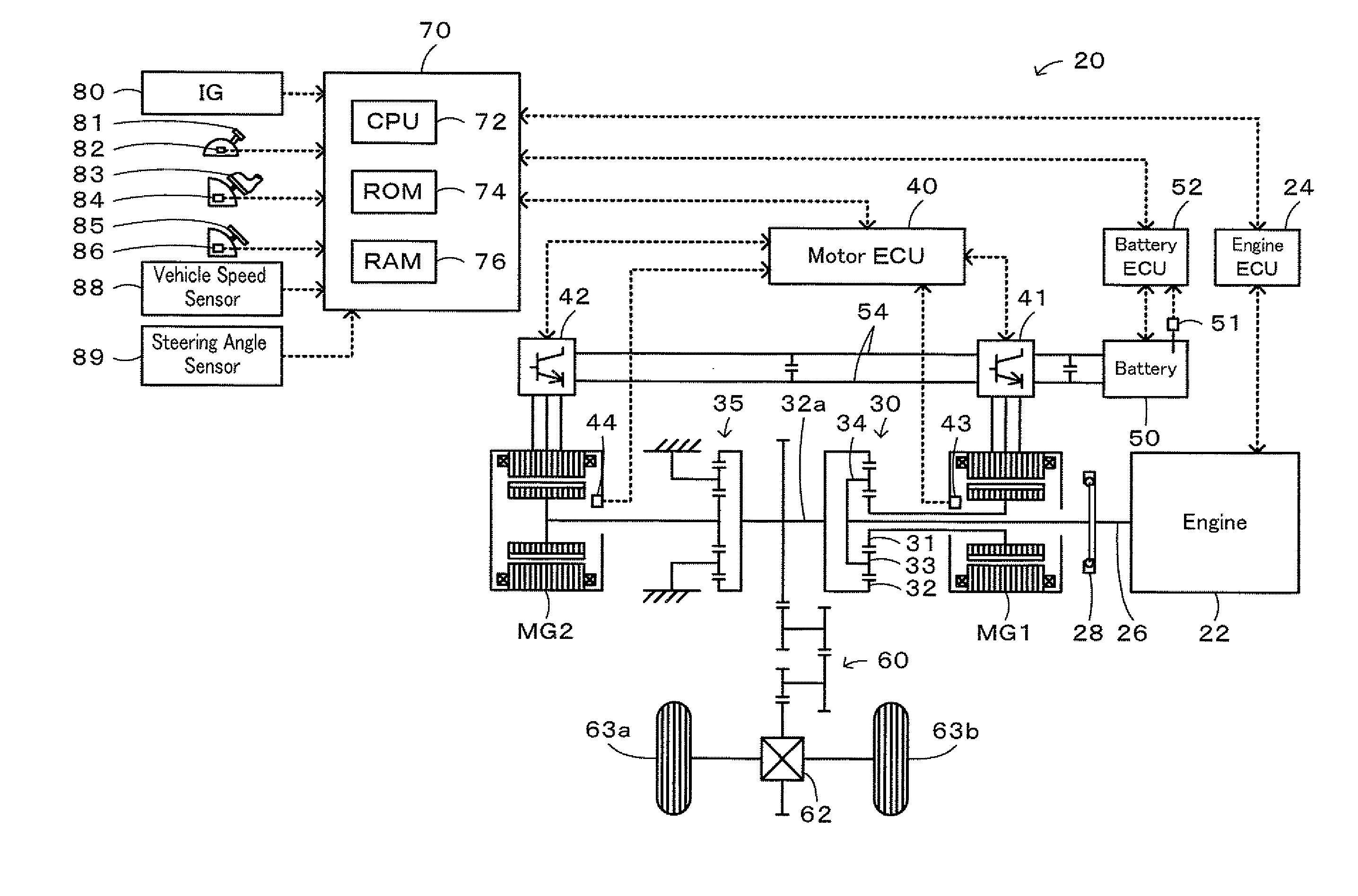
[0028]One mode of carrying out the invention is discussed below as a preferred embodiment. FIG. 1 schematically illustrates the configuration of a hybrid vehicle 20 in one embodiment of the invention. As illustrated, the hybrid vehicle 20 of the embodiment includes the engine 22, a three shaft-type power distribution integration mechanism 30 connected via a damper 28 to a crankshaft 26 or an output shaft of the engine 22, a motor MG1 connected to the power distribution integration mechanism 30 and designed to have power generation capability, a reduction gear 35 attached to a ring gear shaft 32a or a driveshaft linked with the power distribution integration mechanism 30, a motor MG2 connected to the reduction gear 35, and a hybrid electronic control unit 70 configured to control the operations of the whole power output apparatus.

[0029]The engine 22 is constructed as an internal combustion engine designed to consume a hydrocarbon fuel, such as gasoline or light oil, and thereby gener...


PUM


Abstract

Upon the occurrence of the abnormality that the inverter for driving the motor is in the one-phase short circuited state, this inverter is stopped in the three-phase short circuited state and sets the execution torque by subtracting the counter electromotive force application torque that is applied the driveshaft due to the counter electromotive force generated by rotation of the motor and the steering angle application torque corresponding to the steering angle from the torque demand according to the step-on amount of the accelerator pedal. The engine and the inverter for driving the motor is controlled so that the vehicle is driven with the set execution torque. This enables the driving force output to the driveshaft from the engine and the motor to be in accordance with the torque demand.

Description

TECHNICAL FIELD[0001]The present invention relates to a vehicle, a control method of the vehicle, and a driving apparatus. More specifically the invention pertains to a vehicle, a control method of the vehicle, and a driving apparatus included along with an internal combustion engine and an accumulator capable of charge and discharge in a power output apparatus capable of outputting power to a driveshaft.BACKGROUND ART[0002]One proposed configuration of a vehicle has an engine, a first motor, a planetary gear mechanism that an output shaft of the engine and a rotating shaft of the first motor are connected and an axle of the vehicle is linked, and a second motor linked with the axle of the vehicle and constructed as a synchronous motor generator. The proposed vehicle counters abnormality of an inverter for driving the second motor (see, for example, Patent Document 1). In this vehicle, upon occurrence of abnormality that an inverter for driving the second motor connected to front wh...

Claims


Application Information

Patent Timeline
IPC IPC(8): G06F19/00B60K6/442B60K6/445B60K6/448B60K6/52B60L50/15B60L50/16B60W10/08B60W20/00
CPCB60K1/02Y02T10/7077B60K6/445B60K6/448B60K6/52B60L3/003B60L11/123B60L11/14B60L2240/24B60L2240/421B60L2240/423B60L2240/486B60W10/06B60W10/08B60W20/00B60W2510/081B60W2520/10B60W2540/10B60W2540/12B60W2540/16B60W2710/0644B60W2710/0666B60W2710/083B60W2710/105Y02T10/6217Y02T10/6239Y02T10/6243Y02T10/6265Y02T10/6286Y02T10/642B60K6/365B60L50/61B60L50/16Y02T10/62Y02T10/64Y02T10/7072Y02T10/70B60W2540/18
Inventor MITSUTANI, NORITAKESHIRAISHI, WATARU
Owner TOYOTA JIDOSHA KK
Learn More