Completely submerged wave energy converter

a wave energy converter, completely submerged technology, applied in the direction of electric generator control, machines/engines, mechanical equipment, etc., can solve the problems of low efficiency, high cost of maintenance, use and diffusion of wave energy converters, etc., and achieve the effect of satisfying the resistance to extremes

Inactive Publication Date: 2010-07-01
40SOUTH ENERGY
View PDF19 Cites 25 Cited by
  • Summary
  • Abstract
  • Description
  • Claims
  • Application Information

AI Technical Summary

Benefits of technology

[0015]satisfactory resistance to extremely severe weather.
[0016]This object is achieved with the improved wave energy converter according to the present invention, the essential characteristics of which are defined in the first of the accompanying claims.

Problems solved by technology

However, known WECs suffer from many shortcomings, which have so far restrained their use and diffusion.
Basically, the main problems are related with a low efficiency, a complex design, and / or a costly maintenance.
Therefore, they cannot be positioned where the waves are biggest and with the highest energy potential.
Moreover, the on-shore or near-shore ones are bulky and hardly compatible with environmental protection.
Finally, as mentioned, the majority of the known devices use a surface float to extract energy from the wave motion or in any case they have a substantial part of their volume above the surface of the water at least during some part of the wave cycle, which can expose them excessively to severe weather and to drag due to wind and small waves.
Due to the presence of surface elements which have necessarily a limited size, there is also a structural limitation to the amount of energy which a single device can harvest.

Method used


Image

  • Completely submerged wave energy converter
  • Completely submerged wave energy converter
  • Completely submerged wave energy converter

Examples


first embodiment

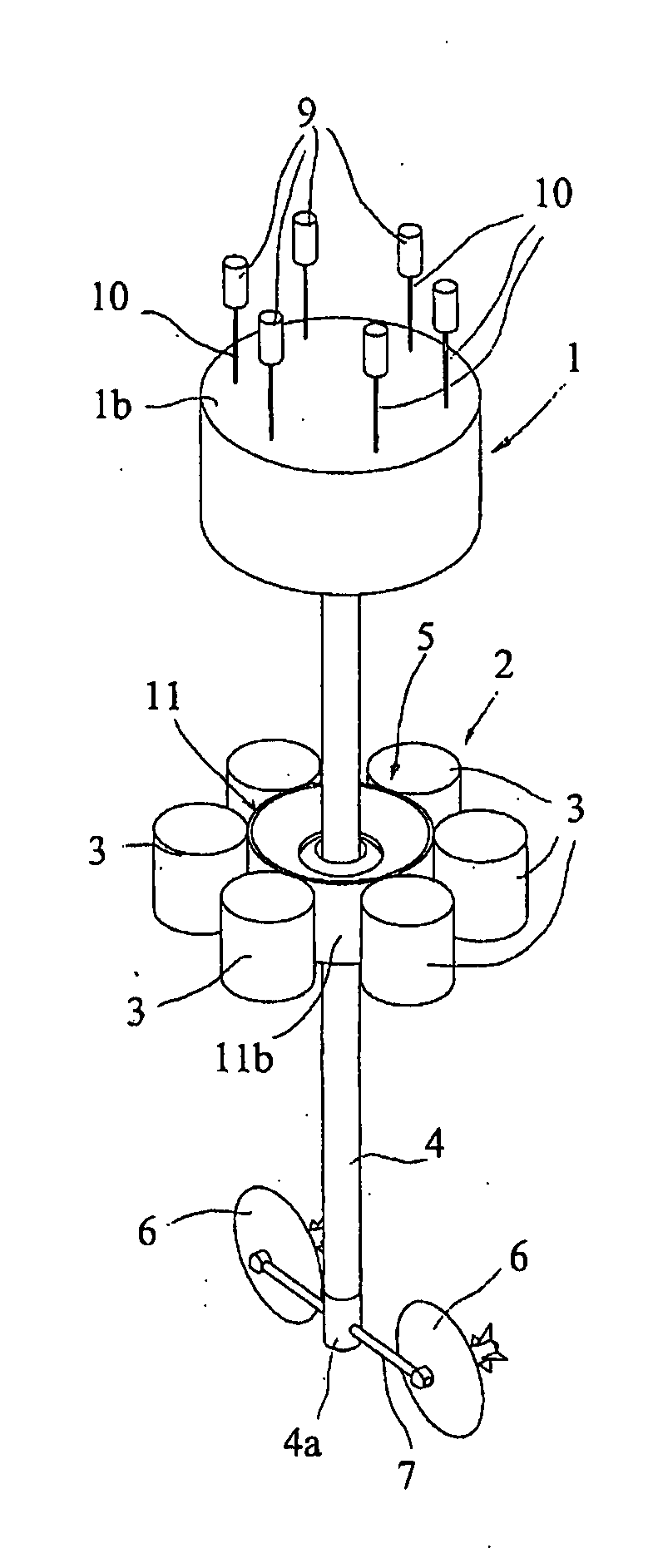
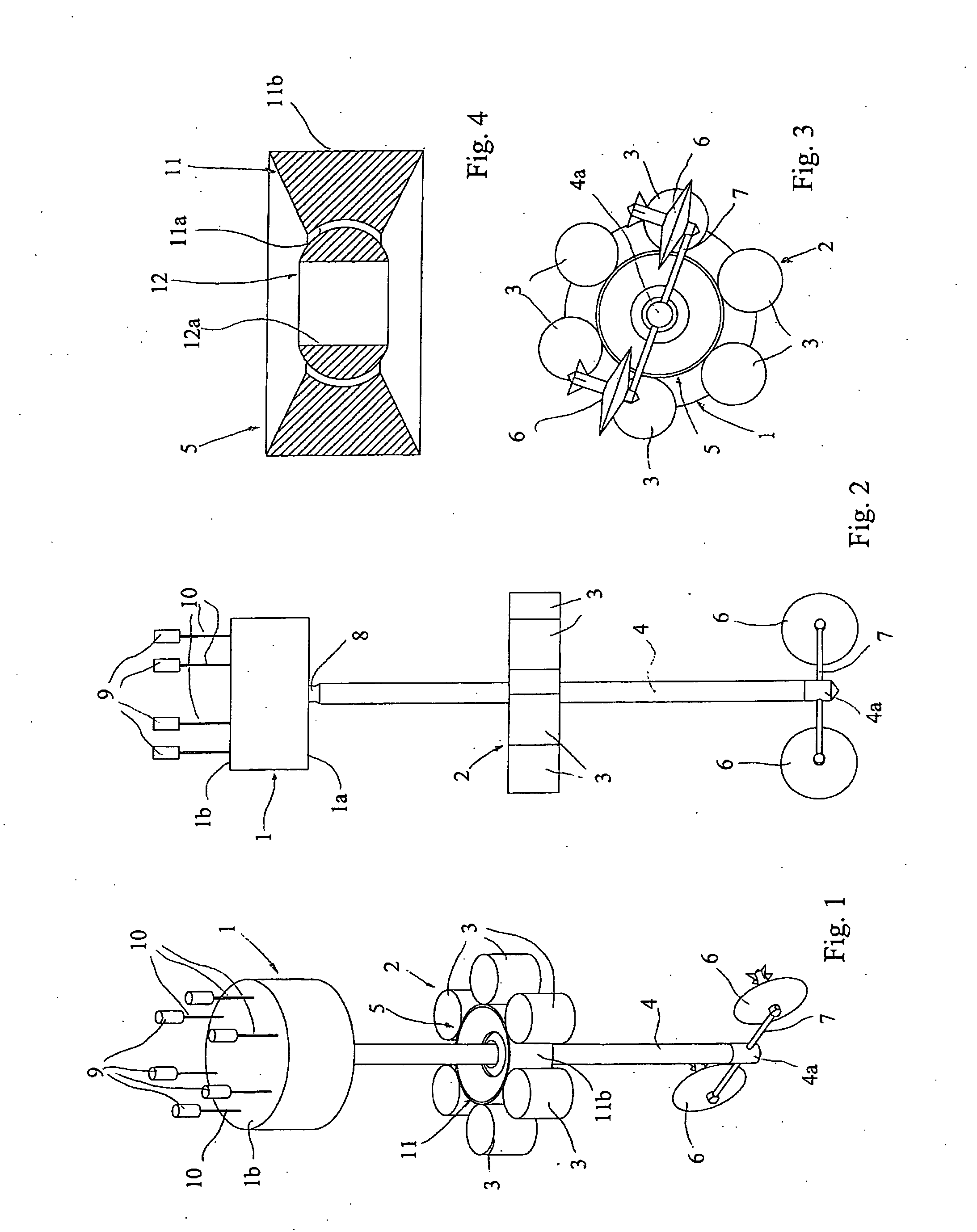
[0033]With reference to FIGS. 1 to 4, the improved wave energy converter according to the invention comprises the following main parts: an upper submerged member 1 (e.g. a cylindrical tank containing mainly water and air, with inertial mass as low as possible); a lower submerged member 2, e.g. comprising six smaller cylindrical tanks 3 containing mainly water and air, rigidly linked together in a circular configuration around a generally cylindrical, central linking piece 5; a pole 4 extending between the upper member 1 and the lower member 2 along the common axis thereof, projecting beyond the lower member 2 and internally provided with an appropriate counterweight system (not shown), at some point along its length corresponding to the average position of the lower submerged member 2; and two turbines 6 mounted on respective ends of a transversal rod 7, integrally and orthogonally crossing the pole 4 in correspondence with the free, lower end thereof.

[0034]The pole can also take th...

second embodiment

[0046]Under a complete wave cycle, the resultant of the forces exerted on the lower submerged member 2 will be approximately vertical and will depend only on the energy and shape of the waves affecting the apparatus. Therefore, in order to keep the lower member 2 at a constant average position, it will be sufficient to have a control system which considers its average position after many wave cycles, and the interventions will be incremental and small compared to the energy of the waves acting on the apparatus. In particular, if the shape and energy of the waves remain constant for a while, the apparatus will reach equilibrium and no further interventions will be needed to stabilize the lower member 2. The control system may be a static device of the kind of the buoyancy elements 9 (see the second embodiment described further on) or even simply consisting of variable buoyancy devices driven by a computerized control device.

[0047]The length of the pole 4 for an oceanic apparatus coul...

third embodiment

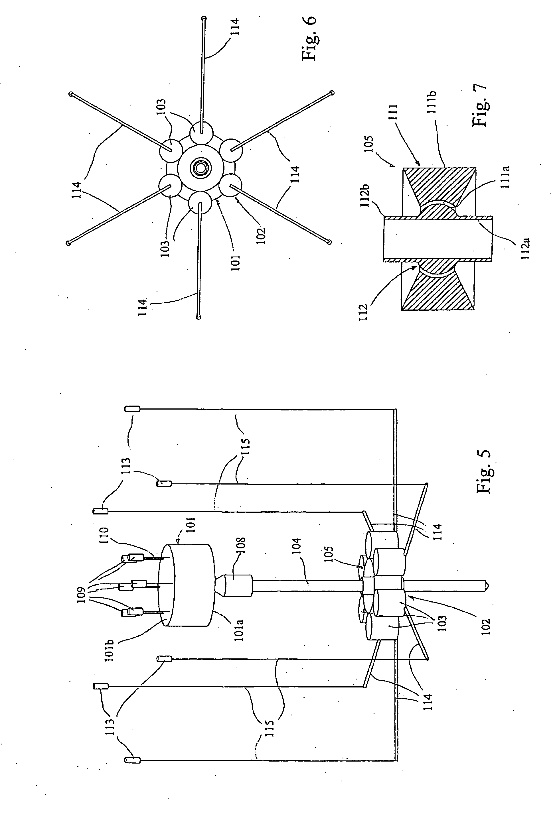
[0057]A further alternative is to connect the upper and lower submerged members via an extensible pole, of the type described further on for a third embodiment, provided with energy extraction systems that exploit the reciprocating extension and contraction movement of the pole. In this way, one can get rid of the energy extraction devices in the linking piece 105 itself, and the pole 104 can end in the linking piece instead of passing through and beyond it. This makes the apparatus more compact, though with the drawback of a more complex structure of the pole. Under exceptionally big waves the whole apparatus will move, as in this case also the lower member will be interested by the wave action. This reduces the possibility of a motion capable of disassembling the apparatus.

[0058]In any case, a possible separation of the two parts will not be destructive, and the apparatus can afterwards be reassembled by letting the pole go back through its housing in the linking piece (or connect...


PUM


Abstract

A wave energy converter apparatus comprising at least two members joined mutually by a connector movable so as to allow mutual displacement of the members in response to waves in water where the apparatus is located. The apparatus also includes an energy converter for converting motion of the connector to electrical energy, and a device for storing and/or transporting elsewhere the energy produced. Preferably, the members are non-floating and completely submerged, thereby causing the apparatus, as a whole, to be neutrally buoyant. A member is additionally provided for maintaining each of the submerged members substantially at rest relative to the surrounding water with which they are in contact, such that the members move under wave action substantially in the same manner as an undisturbed water particle located in the same region, the at least two submerged members being spaced mutually by the connector so as to assume respective positions affected differently by the wave-induced water motion.

Description

FIELD OF THE INVENTION[0001]The present invention relates to the field of wave energy converters (WEC), that is to say those installations or devices for the generation of electricity from sea waves.BACKGROUND OF THE INVENTION[0002]Various kinds of wave energy converters have been proposed in the prior art. However, known WECs suffer from many shortcomings, which have so far restrained their use and diffusion.[0003]Basically, the main problems are related with a low efficiency, a complex design, and / or a costly maintenance. These problems are caused by a number of factors, to some extent related to each other.[0004]Firstly, known WECs use mainly the vertical component of the wave motion. Since the wave motion is generally circular, a significant component of the motion is wasted, see for example the devices in U.S. Pat. No. 4,453,894, U.S. Pat. No. 6,857,266, WO2004065785, U.S. Pat. No. 4,232,230, U.S. Pat. No. 4,672,222, U.S. Pat. No. 5,411,377, and the devices Pelamis, AWS WEC and...

Claims


Application Information

Patent Timeline
Patent Type & Authority Applications(United States)
IPC IPC(8): F03B13/10F03B13/16
CPCF03B13/20Y02E10/38F05B2240/97Y02E10/30F03B13/14F03B13/22
Inventor GRASSI, MICHELE
Owner 40SOUTH ENERGY
Why Eureka
Try Eureka