
Non-Volatile Memory And Method For Sensing With Pipelined Corrections For Neighboring Perturbations

a non-volatile, memory technology, applied in static storage, digital storage, instruments, etc., can solve the problems of unsuitable mobile and handheld environment, prone to mechanical failure, bulky disk drives, etc., to reduce the total setup time and improve sensing performance

Inactive Publication Date: 2010-07-01
SANDISK TECH LLC
View PDF20 Cites 28 Cited by
  • Summary
  • Abstract
  • Description
  • Claims
  • Application Information

AI Technical Summary

Benefits of technology

[0019]In the present inventive scheme, the offset scanning voltage applies the various compensation levels on the adjacent word line WLn+1 in one sweep and the word line delay period for each infinitesimal compensation level will be “pipelined” one after each other. This results in substantial reduction of the total setup time for all the compensation levels and therefore in improved sensing performance.

Problems solved by technology

Conventional mass storage, based on rotating magnetic medium such as hard drives and floppy disks, is unsuitable for the mobile and handheld environment.
This is because disk drives tend to be bulky, are prone to mechanical failure and have high latency and high power requirements.
These undesirable attributes make disk-based storage impractical in most mobile and portable applications.
While increasing parallelism improves read or sensing performance, prior sensing techniques are becoming increasingly time-consuming with the increase in storage density by having each storage element storing more and more bits of data.

Method used


Image

  • Non-Volatile Memory And Method For Sensing With Pipelined Corrections For Neighboring Perturbations
  • Non-Volatile Memory And Method For Sensing With Pipelined Corrections For Neighboring Perturbations
  • Non-Volatile Memory And Method For Sensing With Pipelined Corrections For Neighboring Perturbations

Examples


Embodiment Construction

Memory System

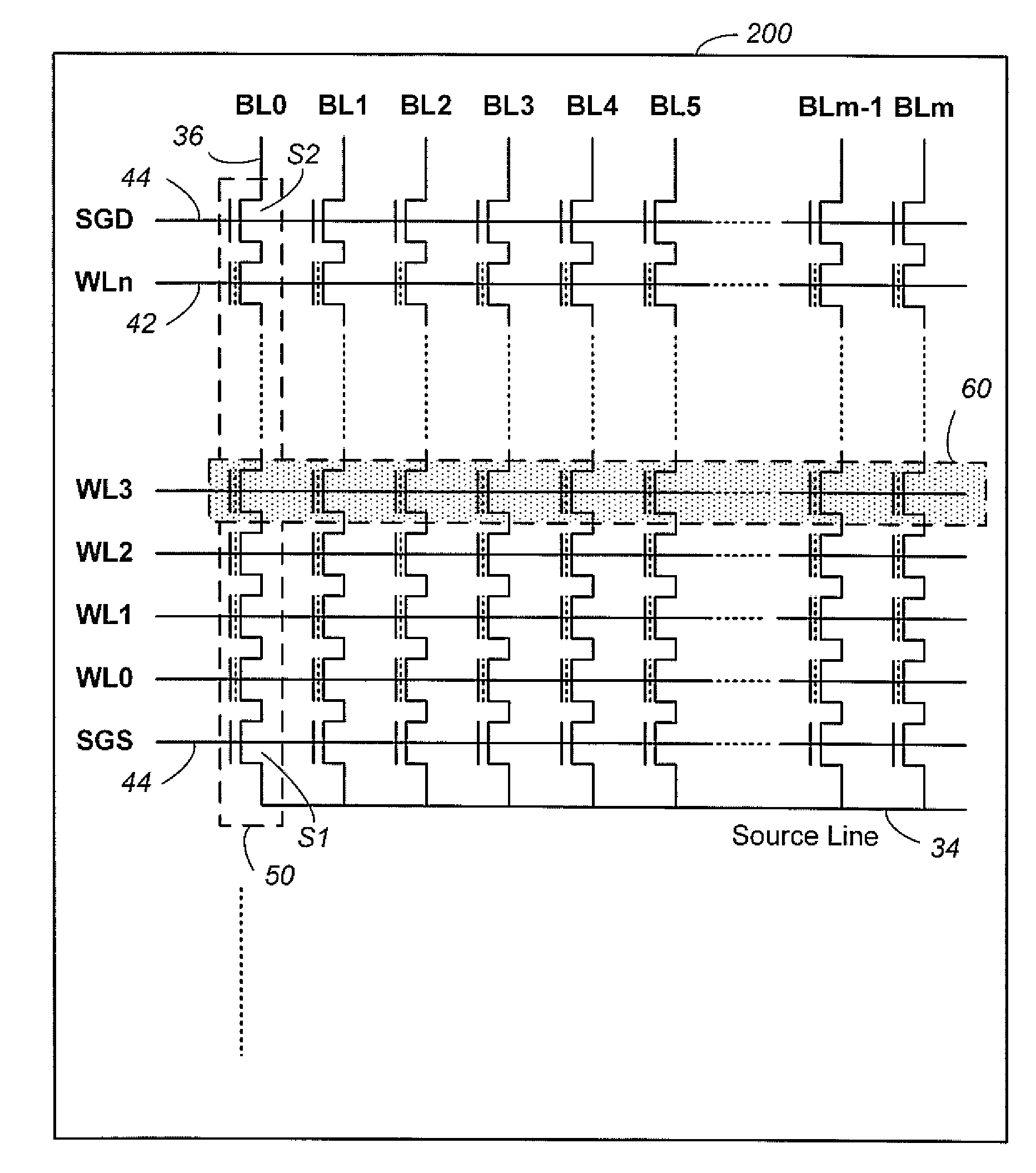
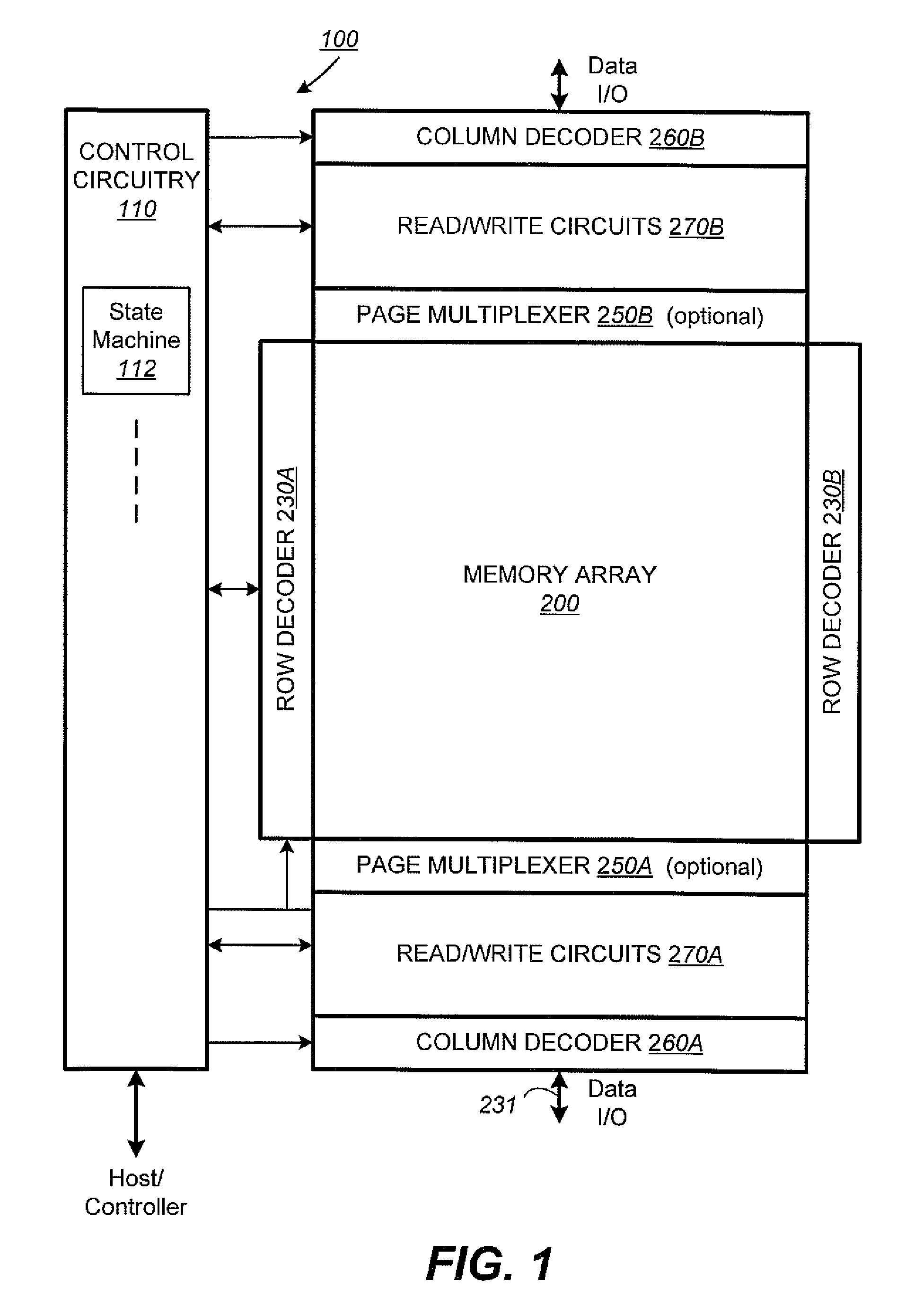
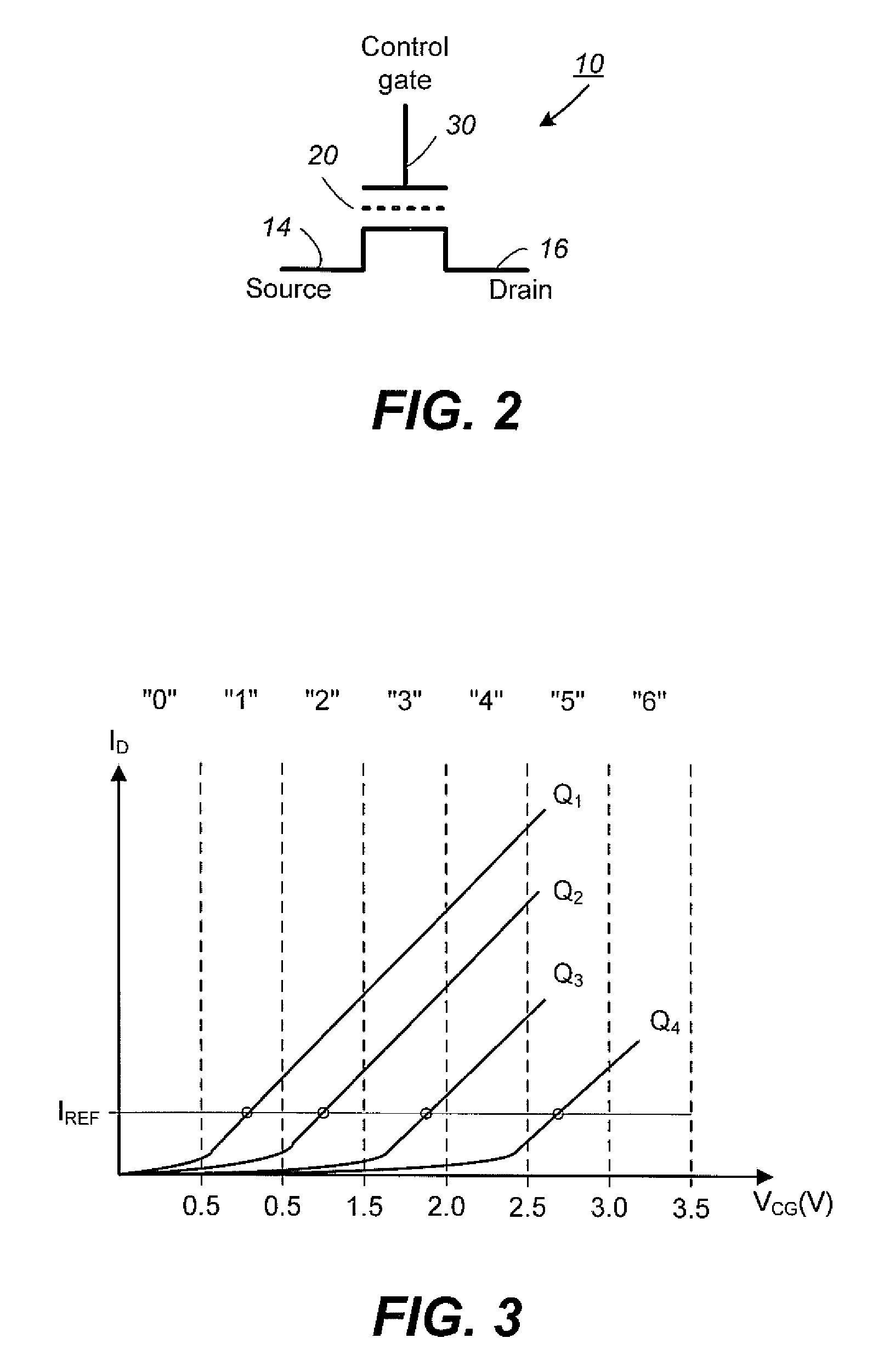
[0056]FIG. 1 to FIG. 12 provide example memory systems in which the various aspects of the present invention may be implemented or illustrated.

[0057]FIG. 13 to FIG. 21 illustrate context and details of the various embodiments according to a first aspect of the present invention of time-domain sensing.

[0058]FIG. 22 to FIG. 30 illustrate context and details of the various embodiments according to a second aspect of the present invention in which the time-domain sensing technique is applied to sensing on a current word line while compensating for perturbations from an adjacent word line.

[0059]FIG. 1 illustrates schematically the functional blocks of a non-volatile memory chip in which the present invention may be implemented. The memory chip 100 includes a two-dimensional array of memory cells 200, control circuitry 210, and peripheral circuits such as decoders, read / write circuits and multiplexers.

[0060]The memory array 200 is addressable by word lines via row decoders 23...


PUM


Abstract

A page of non-volatile multi-level storage elements on a word line WLn is sensed in parallel while compensating for perturbations from a neighboring page on an adjacent word line WLn+1. First, the programmed thresholds of storage elements on WLn+1 are sensed in the time domain and encoded as time markers. This is accomplished by a scanning sense voltage increasing with time. The time marker of a storage element indicates the time the storage element starts to conduct or equivalently when the scanning sense voltage has reached the threshold of the storage element. Secondly, the page on WLn is sensed while the same scanning voltage with an offset level is applied to WLn+1 as compensation. In particular, a storage element on WLn will be sensed at a time indicated by the time marker of an adjacent storage element on WLn+1, the time when the offset scanning voltage develops an appropriate compensating bias voltage on WLn+1.

Description

CROSS REFERENCE TO RELATED APPLICATIONS[0001]This application is related to the U.S. patent application Ser. No. ______, entitled “Non-Volatile Memory And Method With Continuous Scanning Time-Domain Sensing” by Raul Adrian Cernea, filed concurrently herewith, on Dec. 31, 2008, which application is incorporated herein in its entirety by this reference.FIELD OF THE INVENTION[0002]This invention relates generally to non-volatile semiconductor memory such as electrically erasable programmable read-only memory (EEPROM) and flash EEPROM, and specifically to sensing operations performed at high speed in the time-domain.BACKGROUND OF THE INVENTION[0003]Solid-state memory capable of nonvolatile storage of charge, particularly in the form of EEPROM and flash EEPROM packaged as a small form factor card, has recently become the storage of choice in a variety of mobile and handheld devices, notably information appliances and consumer electronics products. Unlike RAM (random access memory) that i...

Claims


Application Information

Patent Timeline
IPC IPC(8): G11C16/06
CPCG11C16/26G11C16/02G11C16/30
Inventor CERNEA, RAUL-ADRIAN
Owner SANDISK TECH LLC
Learn More