System and method for thin film deposition

a technology of thin film and reaction chamber, applied in chemical vapor deposition coating, coating, metallic material coating process, etc., can solve the problems of large number of precursor cycles, process self-limiting, and inability to optimize reaction chamber assembly design and operating modes for self-limiting processes, so as to reduce the pump down time and eddy current, reduce the effect of eddy current and increase flow velocity

Active Publication Date: 2010-07-01
VEECO INSTR
View PDF70 Cites 59 Cited by
  • Summary
  • Abstract
  • Description
  • Claims
  • Application Information

AI Technical Summary

Benefits of technology

[0019]The present invention provides a reaction chamber assembly suitable for forming thin film deposition layers onto solid substrates. The reaction chamber assembly of the present invention is improved over conventional reaction chamber assemblies by delivering a substantially uniform flow of source material into a reaction chamber across the entire width or length of the substrates supported inside the reaction chamber for coating. The reaction chamber assembly of the present invention further improves over conventional reaction chamber assemblies by causing the flow of source material to flow over the substrates being coated with a substantially uniform flow direction and velocity. The reaction chamber assembly of the present invention further improves over conventional reaction chamber assemblies by reducing eddy currents in the flow of source materials. The reaction chamber assembly of the present invention further improves over conventional reaction chamber assemblies by compressing outflow gasses in an output plenum to increase flow velocity proximate to an exit port. The configuration of gas flow conduits and the substrate support area reduces pump down time and eddy currents.
[0026]The reaction chamber assembly may be formed by an outer wall assembly for enclosing an outer volume. An outer aperture passes through one of the outer walls to the outer volume to provide access for loading a removable and cleanable liner into the outer volume through the outer aperture. The outer aperture may be in a front or a back outer wall. The removable liner encloses the reaction chamber and is configured to provide the substrate support area therein. The removable liner includes liner walls and a chamber aperture passing through a front wall of the liner walls to provide access to the substrate support area through the chamber aperture. The removable liner is configured to be installed into and removed from the outer volume through the front or a back outer aperture. An access door is disposed on a front wall of the reaction chamber assembly and movable from an open position, to expose the chamber aperture for loading and unloading substrates into the substrate support area through the front wall, or to a closed position for substantially gas sealing the chamber aperture with a chamber aperture seal element attached to the access door. The access door includes sealing elements for sealing the outer volume and the reaction chamber when the door is closed. A back panel and sealing elements may be provided to gas seal the back outer aperture. The input and output plenums may be disposed inside the removable liner. The input and output plenums may also include internal plenum baffles disposed inside the plenum conduits for directing the flow along desired flow paths inside the plenum conduits. The plenum baffles are disposed to increase the uniformity of the flow of source material across the input conduit aperture width.
[0027]The present invention further provides improved methods for depositing thin film layers of solid material onto exposed surfaces of a substrate housed inside the reaction chamber by supporting the substrate on a horizontally disposed substrate tray with a surface being coated facing vertically upward. The substrate tray or trays have a width equal to or slightly larger than the substrate area support width. The reaction chamber assembly is configured to receive a flow of source material from the source into a first end of an input plenum conduit that is disposed between the source and the reaction chamber. The input plenum conduit is shaped with a first cross section formed to expand the volume of the flow of source material as it flow through the input plenum conduit. The input conduit receives the flow of source material from the source at a first input plenum conduit end and delivers the expanded flow of source material out of a second input conduit end into the reaction chamber. The second input conduit end forms an aperture that delivers the flow of source material into the reaction chamber over the entire support width.

Problems solved by technology

These processes are self-limiting because only one precursor is introduced into the reaction chamber at a time.
However, in most early transitions to convert CVD and other non-limiting thin film deposition processes and reaction chamber assemblies designs to self-limiting thin film deposition processes and reaction chamber designs more suitable for ALE, ALD and other self limiting reactions, the reaction chamber assembly designs and operating modes have not been optimized for the self-limiting processes.
A disadvantage of self-limiting thin film deposition processes is that a large number of precursor cycles is required to build up appreciable film thickness since self-limiting film layer thickness is typically less than about 10 Å per monolayer.
A further disadvantage of self-limiting thin film deposition processes is that the formation of each monolayer may require four gas introduction steps, e.g. an initial chamber purge, a first precursor introduction, a chamber purge and a second precursor introduction.

Method used


Image

  • System and method for thin film deposition
  • System and method for thin film deposition
  • System and method for thin film deposition

Examples


first embodiment

ALD System First Embodiment

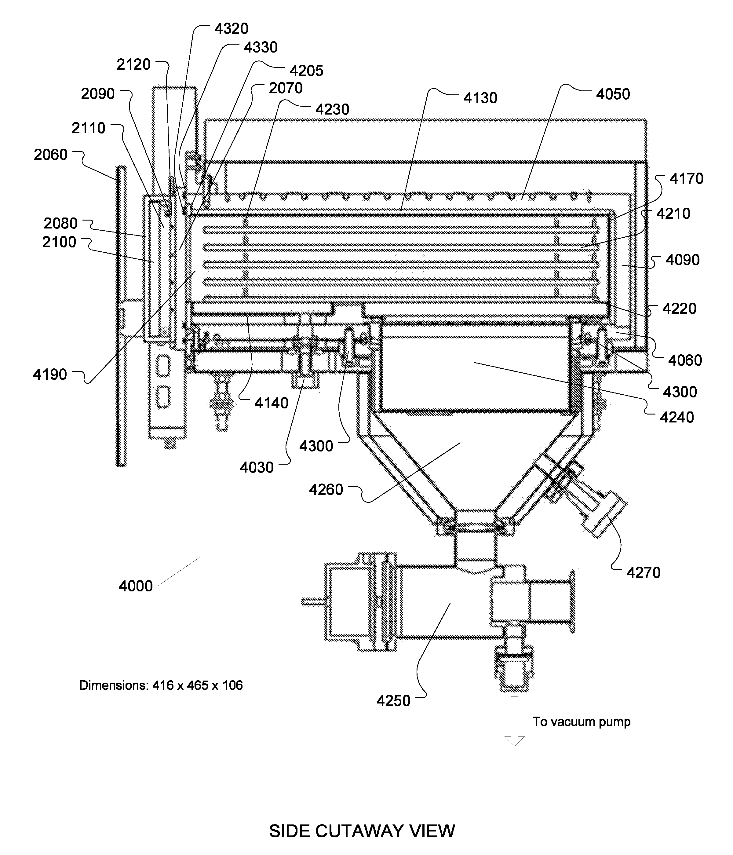
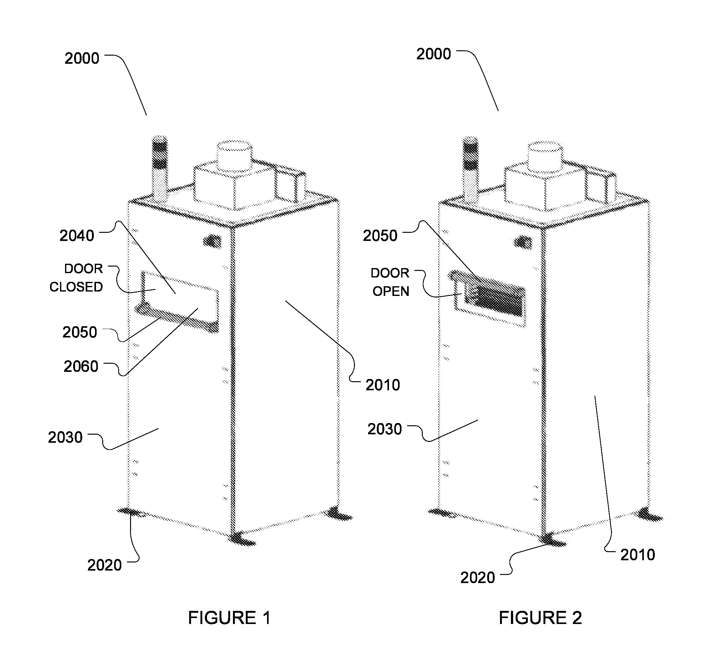
[0051]Referring to FIGS. 1 and 2, an exemplary first embodiment of an atomic layer deposition system (ALD) (2000) configured according to the present invention is constructed with a floor standing system cabinet (2010) supported on four feet (2020) having a front face (2030) that includes an access door assembly (2040). The access door assembly (2040) includes a door handle (2050) mounted on an outer door panel (2060). Both the outer door panel (2060) and the door handle (2050) are thermally insulated to protect an operator when handling the door handle (2050). The access door assembly (2040) is shown in a closed or operating position in FIG. 1 and in an open or loading / unloading position in FIG. 2. The access door assembly (2040) provides access through the system cabinet (2010) to a gas deposition or reaction chamber (4000) described below. The gas deposition chamber (4000) is housed inside the system cabinet (2010) behind the access door assembly (2040)...

second embodiment

ALD System Second Embodiment

[0092]A second exemplary embodiment of the present invention comprises a dual chamber gas deposition system (1000) shown in isometric view with the external skins removed in FIG. 11. The system (1000) includes a front face (1180) which is used for loading substrates into each of two gas deposition chambers (1120) and (1150). In a preferred embodiment, the front face (1180) interfaces with a clean room wall and the substrates are loaded and unloaded from inside the clean room through the clean room wall. For that reason, the removable liners installed into and removable from each of the gas deposition chambers of the second exemplary embodiment are installed and removed through a back face, opposed to the front face (1180).

[0093]A right side face (1130) includes a single user interface device (1200) which can be used to enter commands for operating both of the gas deposition chamber assemblies (1120) and (1150). In alternate embodiments, each gas depositio...

third embodiment

ALD System Third Embodiment

[0126]Referring now to FIGS. 14 and 18-19, a third embodiment of a chamber assembly (8100) according to the present invention is configured substantially like the reaction chamber (3000) described above except that the X-axis dimension of the chamber assembly (8100) is more than doubled and a removable liner (8110) is configured with six substrate trays (8120) instead on one substrate support surface. The substrate trays (8120) are supported in two stacks of three trays each with side by side substrate trays being substantially coplanar. Substrate trays (8120) are supported at each end thereof by a plurality of tray supports (8130) fixedly attached to the removable liner (8110). Each substrate tray (8120) supports a single substrate (7000) in a substantially horizontal orientation with a surface to be coated facing up.

[0127]The removable liner (8110) houses a reaction chamber (8140) suitable for batch coating six rectangular substrates (7000) supported on ...


PUM

PropertyMeasurementUnit
vacuum pressureaaaaaaaaaa
melting temperatureaaaaaaaaaa

Abstract

A reaction chamber assembly suitable for forming thin film deposition layers onto solid substrates includes a reaction chamber and an input plenum for receiving source material from gas source containers and delivering a flow of source material into the reaction chamber uniformly distributed across a substrate support width. An output plenum connected between the reaction chamber and a vacuum pump uniformly removes an outflow of material from the reaction chamber across the substrate support width. The input plenum is configured to expand a volume of the source material and deliver the source material to the substrate support area with uniform source material flow distribution across the substrate support width. The output plenum is configured to remove the outflow material across the entire substrate support width and to compress the volume of outflow material prior to the outflow material exiting the output plenum. The resulting source material flow over substrates supported in the substrate support area is uniformly distributed across the substrate support width and unidirectional with a uniform flow velocity. The configuration of the reaction chamber assembly reduces pump down times.

Description

CROSS REFERENCE TO RELATED U.S. PATENT APPLICATIONS [0001]The present application claims priority under 35 U.S.C. §119(e) to provisional U.S. Patent Application Ser. No. 61 / 197,948 (Docket No. 0082-PHOENIX) filed Nov. 1, 2008, and provisional U.S. Patent Application Ser. No. 61 / 208,875 (Docket No. 0087-TAHITI) filed Feb. 27, 2009, both of which are incorporated herein by reference in its entirety and for all purposes.COPYRIGHT NOTICE [0002]A portion of the disclosure of this patent document may contain material that is subject to copyright protection. The copyright owner has no objection to the facsimile reproduction by anyone of the patent document or the patent disclosure, as it appears in the Patent and Trademark Office patent files or records, but otherwise reserves all copyright rights whatsoever. The following notice shall apply to this document: Copyright 2009, Cambridge NanoTech, Inc.BACKGROUND OF THE INVENTION[0003]1. Field of the Invention[0004]The present invention relate...

Claims


Application Information

Patent Timeline
Patent Type & Authority Applications(United States)
IPC IPC(8): C23C16/458
CPCC23C16/4401C23C16/45582C23C16/45546C23C16/45504H01L21/205
Inventor BECKER, JILL S.COUTU, ROGER R.MONSMA, DOUWE J.
Owner VEECO INSTR
Why Eureka
Try Eureka