Systems for providing fluid flow to tissues

Active Publication Date: 2010-07-01
KCI LICENSING INC
View PDF103 Cites 18 Cited by
  • Summary
  • Abstract
  • Description
  • Claims
  • Application Information

AI Technical Summary

Benefits of technology

[0011]In another embodiment, a system for providing reduced pressure therapy and facilitating growth of tissue at a tissue site of a patient is provided that includes a source of reduced pressure for supplying reduced pressure, a scaffold adaptable for implantation at the tissue site, where the scaffold provides a structural matrix for the growth of the tissue and has a luminal surface, a gel or liquid composition deposed on at least a portion of the luminal surface, where the gel or liquid composition is adapted to include microbubbles, a manifold adjacent the scaffold, where the manifold distributes the reduced pressure to the scaffold, and a conduit for providing fluid communication between the manifold and the source of reduced pressure.
[0012]In a further embodiment, a method of providing reduced pressure therapy and facilitating growth of tissue at a tissue site of a patient is provided that includes implanting a scaffold at the tissue site, where the scaffold provides a structural matrix for the growth of the tissue and comprises a gel or liquid composition on a luminal surface, where the gel or liquid composition is adapted to include microbubbles, applying reduced pressure to the scaffold, and disrupting a substant

Problems solved by technology

The later stages of the wound healing response are dependent upon the previous stages, with increasing complexity in the temporal patterning of and interrelationships between each component of the response.
Although some level of success has been achieved using this approach, several key challenges remain.
One main challenge is that the timing and coordinated influence of each cytokine and growth factor within the wound healing response complicate the ability to add individual exogenous factors at the proper time and in th

Method used


Image

  • Systems for providing fluid flow to tissues
  • Systems for providing fluid flow to tissues
  • Systems for providing fluid flow to tissues

Examples


Embodiment Construction

[0022]In the following detailed description of the illustrative embodiments, reference is made to the accompanying drawings that form a part hereof. These embodiments are described in sufficient detail to enable those skilled in the art to practice the invention, and it is understood that other embodiments may be utilized and that logical structural, mechanical, electrical, and chemical changes may be made without departing from the spirit or scope of the invention. To avoid detail not necessary to enable those skilled in the art to practice the embodiments described herein, the description may omit certain information known to those skilled in the art. The following detailed description is, therefore, not to be taken in a limiting sense, and the scope of the illustrative embodiments are defined only by the appended claims.

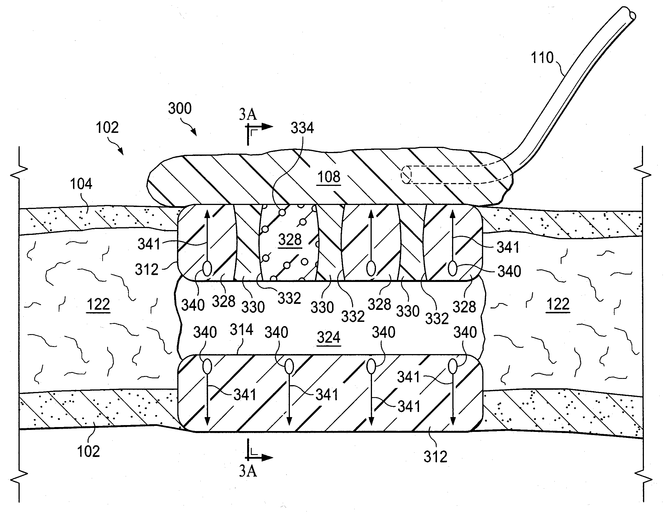
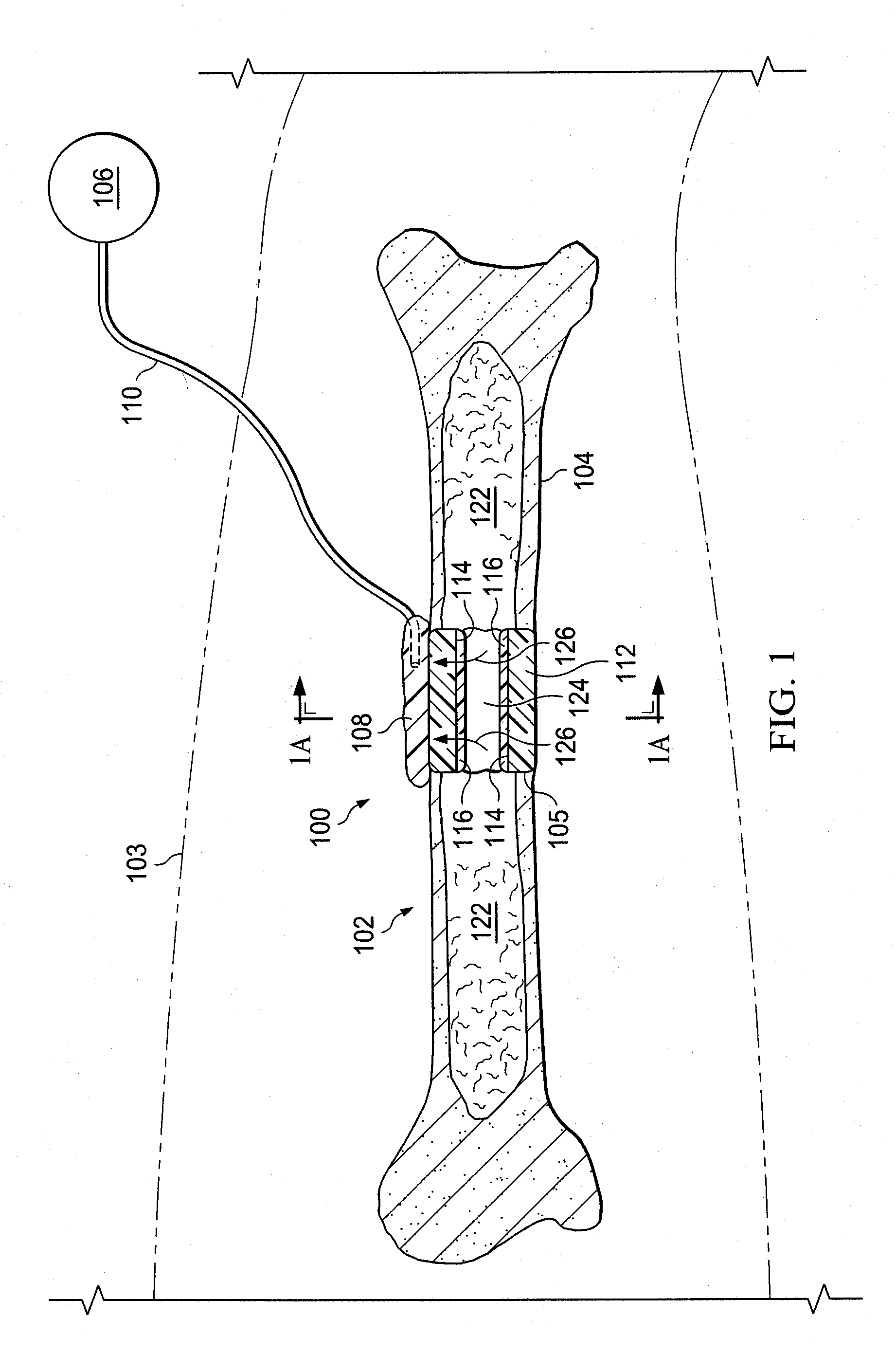
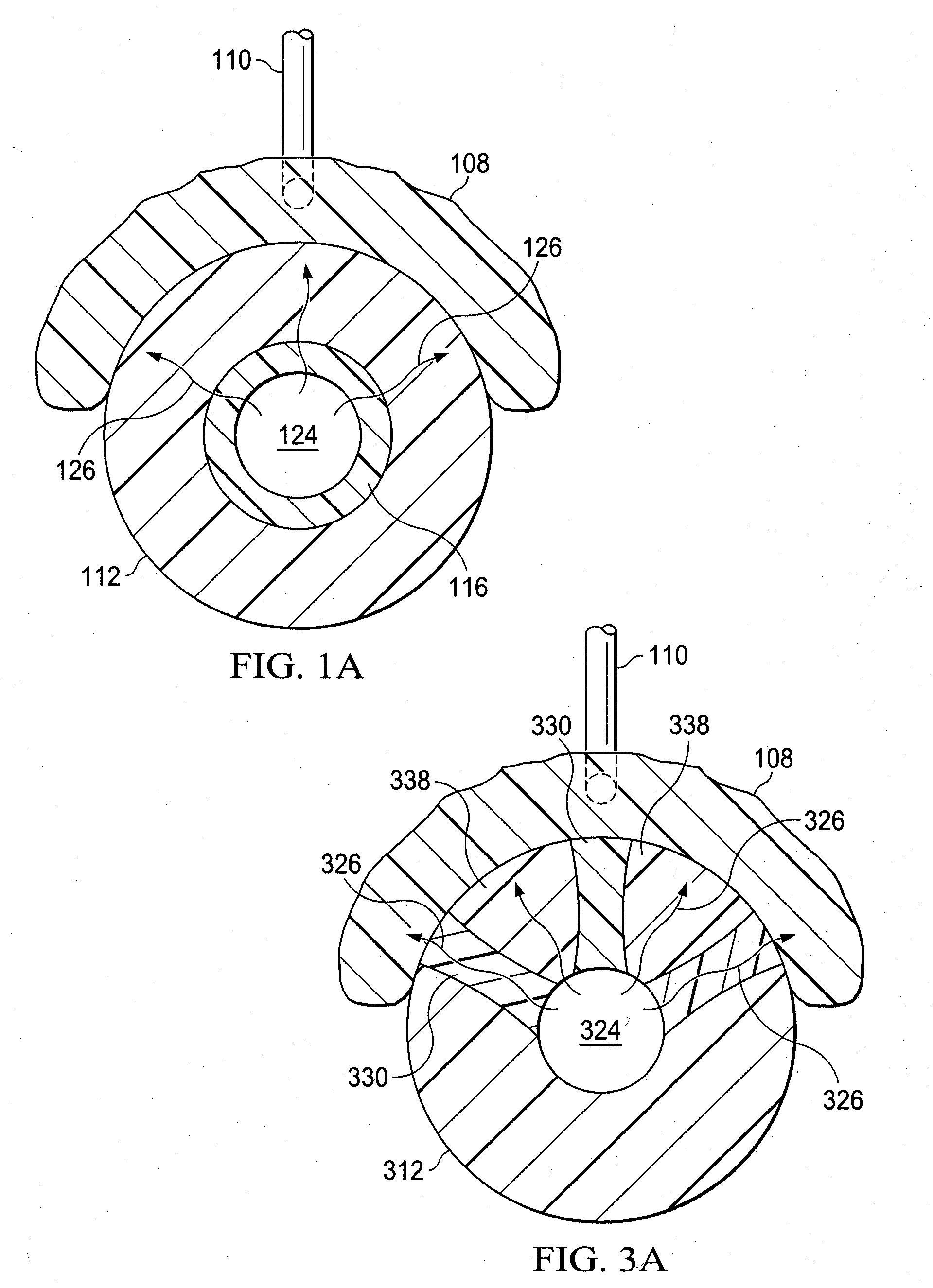
[0023]Referring to FIGS. 1 and 2A-2C, a reduced pressure therapy system 100 for applying reduced pressure to a tissue site 102 of a patient 103 includes a reduced...


PUM

PropertyMeasurementUnit
Pressureaaaaaaaaaa
Amphiphilicaaaaaaaaaa
Shapeaaaaaaaaaa

Abstract

Provided is an apparatus that includes a scaffold with a gel or liquid composition deposed on at least a portion of a luminal surface, the gel or liquid composition adapted to include microbubbles. Also provided is a system that includes a source of reduced pressure, the above scaffold, a manifold adjacent the scaffold, and a conduit for providing fluid communication between the manifold and the source of reduced pressure. Additionally provided is a method that includes implanting the above scaffold at the tissue site and disrupting a substantial portion of the microbubbles to induce fluid flow to the scaffold. Further provided is an apparatus that includes a scaffold that comprises a slowly degradable material and a quickly degradable material. Additionally provided is a system for coupling nerve tissue and a microchip assembly.

Description

CROSS-REFERENCE TO RELATED APPLICATIONS[0001]This application claims the benefit of U.S. Provisional Application No. 61 / 234,692, filed Aug. 18, 2009, U.S. Provisional Application No. 61 / 142,053, filed Dec. 31, 2008, and U.S. Provisional Application No. 61 / 142,065, filed Dec. 31, 2008, all of which are hereby incorporated by reference.BACKGROUND OF THE INVENTION[0002]1. Field of the Invention[0003]The present application relates generally to tissue engineering and in particular to systems and scaffolds suitable for use in treatment of tissue.[0004]2. Description of Related Art[0005]Clinical studies and practice have shown that providing a reduced pressure in proximity to a tissue site augments and accelerates the growth of new tissue at the tissue site. The applications of this phenomenon are numerous, but application of reduced pressure has been particularly successful in treating wounds. This treatment (frequently referred to in the medical community as “negative pressure wound the...

Claims


Application Information

Patent Timeline
IPC IPC(8): A61K38/20A61K38/27A61K38/18A61K38/19A61P17/02A61M1/00
CPCA61M1/0088A61B17/88A61K38/19A61K38/22A61K49/223A61M1/0023A61M27/00A61F13/00068A61F2002/368A61F2/2846A61F13/00063A61F2013/00357A61M37/00A61M37/0092A61N5/062A61F2013/00927A61F2002/2835A61F2002/30784A61K38/18A61M1/92A61M1/915A61M1/84A61P17/02A61M2210/02A61M1/00A61L27/58A61L27/54
Inventor SWAIN, LARRY D.MANWARING, MICHAEL E.CORNET, DOUGLAS A.LEUNG, BRADEN K.
Owner KCI LICENSING INC
Why Eureka
Try Eureka