
Therapeutic agent delivery system

a delivery system and therapeutic agent technology, applied in the field of medical devices, can solve the problems of excessive amount, unsatisfactory, and multiple catheter balloons that may require undetected inflation time and/or dwell time of the catheter, and achieve the effect of increasing the pressure of the expandable portion of the catheter sha

Inactive Publication Date: 2010-07-01
COOK INC
View PDF6 Cites 70 Cited by
  • Summary
  • Abstract
  • Description
  • Claims
  • Application Information

AI Technical Summary

Benefits of technology

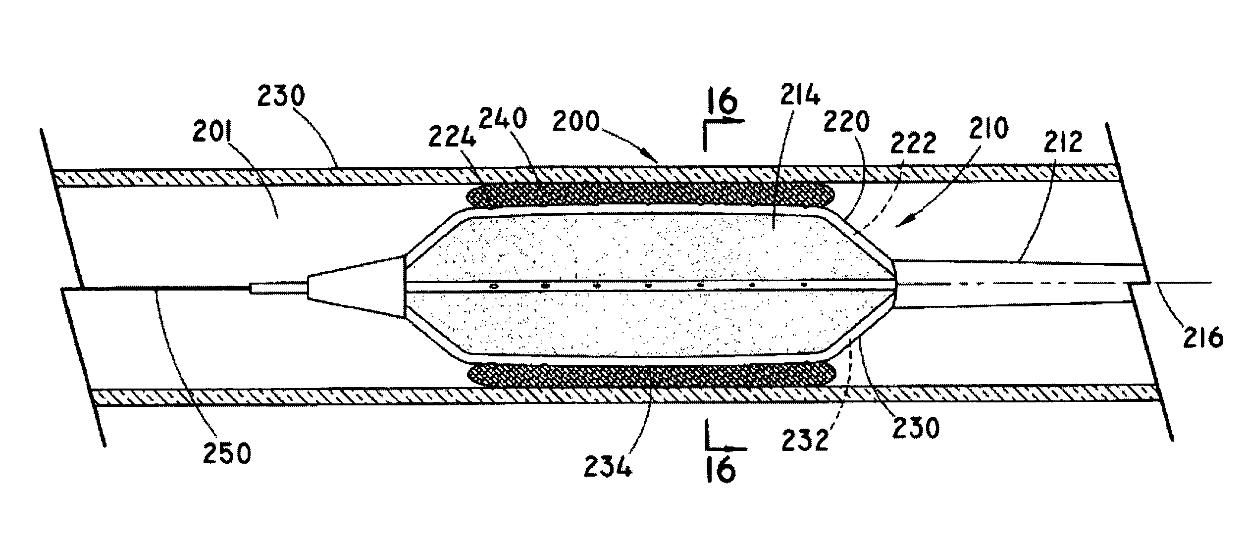
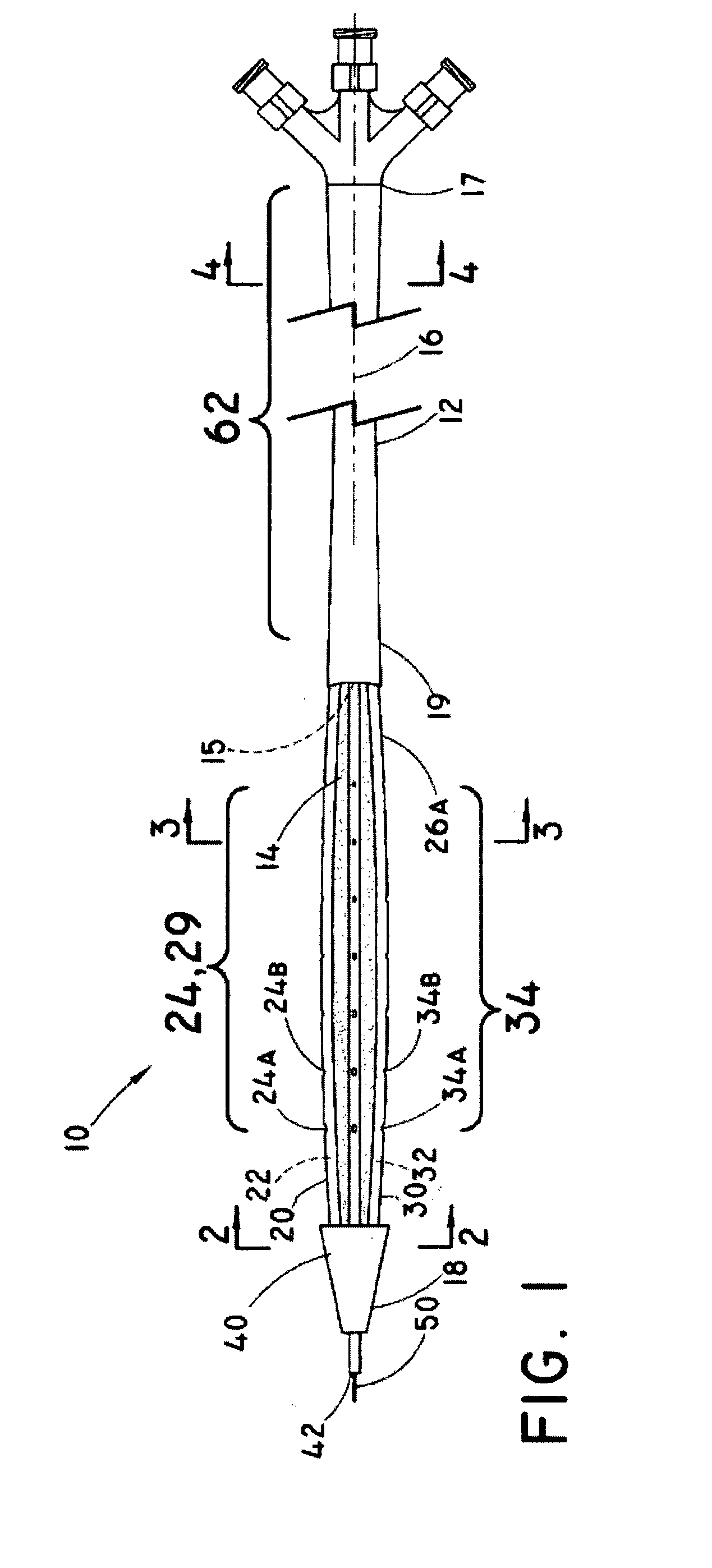
[0018]In a second embodiment, methods of treatment are provided that relate to delivering a therapeutic agent(s) to an interior wall of a body vessel at or near a treatment site using a medical device described according to the first embodiment. In one aspect, methods of delivering a therapeutic agent delivery system are provided that include administration of a therapeutic agent from one or more therapeutic agent delivery ports in a therapeutic agent delivery conduit. The conduit may be attached to a catheter shaft having an expandable portion that is inflatable from a deflated configuration to an inflated configuration. The therapeutic agent delivery system may be inserted into a body vessel. A portion of the therapeutic agent delivery system may be translated within the body vessel until a therapeutic agent delivery conduit with the therapeutic agent delivery port is positioned proximate the treatment site within the body vessel. The expandable portion of the catheter shaft may be inflated within the body vessel until at least the portion of the external surface of the expandable portion contacts the therapeutic agent delivery conduit. The pressure of the expandable portion of the catheter shaft may be increased until the therapeutic agent delivery conduit is pressed into the wall of the body vessel. A therapeutic agent may be injected from the therapeutic agent delivery lumen through the therapeutic agent delivery port to the wall of the body vessel proximate the treatment site. A portion of the body vessel may enclose one or more ports in the conduit, permitting the injected therapeutic agent to remain in an interstitial space between the body vessel wall and the conduit port while the therapeutic agent diffuses into the body vessel wall tissue. In this manner, the therapeutic agent may be absorbed by the body vessel without scoring or cutting the wall of the body vessel. After treatment, the expandable portion of the catheter shaft may be deflated and the therapeutic agent delivery system removed from the body vessel. The therapeutic agent absorbed by the wall of the body vessel may diffuse slowly through multiple layers of the body vessel tissue after treatment, permitting the gradual administration of the therapeutic agent throughout the body vessel after removal of the conduit from the body vessel.

Problems solved by technology

However, at times after PTCA an abrupt closure or more gradual closure of the body vessel occasionally follows such procedure.
Besides restenosis, tumor formation and thrombosis, the formation of a fibrinous clot in a blood vessel, are other common drawbacks associated with stent placement during angioplasty.
However, the inflation of the multiple catheter balloons may require undesirably extended inflation time and / or dwell time of the catheter.
Although the tubular extensions may provide adequate sealing to localize the administration of the therapeutic agent within the body vessel wall, the projections may not ensure even administration of the therapeutic agent along the entire treatment site, and excessive amounts of the therapeutic agent may be needed to ensure adequate treatment.
This may require excessive amounts of therapeutic agent to ensure administration of adequate amount of the therapeutic agent to the wall of the body vessel.
Nevertheless, the use of cutting balloons can damage and traumatize the body vessel wall to a degree of leading to restenosis.
However, these systems and methods require a scoring of the body vessel wall prior to releasing the drug to locations in or beneath the intimal layer of the body vessel wall.
While the scoring of the vessel wall permits delivery of the drug to intimal or subintimal layers surrounding the blood vessel, the scoring process also damages the vessel wall.
This damage to the vessel wall may, in turn, lead to additional complications, such as thrombus formation or inflammation of the scoring site.

Method used


Image

  • Therapeutic agent delivery system
  • Therapeutic agent delivery system
  • Therapeutic agent delivery system

Examples


Embodiment Construction

[0037]As used herein, the term “implantable” refers to an ability of a medical device to be positioned at a location within a body, such as within a body vessel. Furthermore, the terms “implantation” and “implanted” refer to the positioning of a medical device at a location within a body, such as within a body vessel.

[0038]The term “biocompatible” refers to a material that is substantially non-toxic in the in vivo environment of its intended use, and that is not substantially rejected by the patient's physiological system (i.e., is non-antigenic). This can be gauged by the ability of a material to pass the biocompatibility tests set forth in International Standards Organization (ISO) Standard No. 10993 and / or the U.S. Pharmacopeia (USP) 23 and / or the U.S. Food and Drug Administration (FDA) blue book memorandum No. G95-1, entitled “Use of International Standard ISO-10993, Biological Evaluation of Medical Devices Part-1: Evaluation and Testing.” Typically, these tests measure a materi...


PUM


Abstract

This present disclosure relates to a medical device and method capable of locally administering therapeutic agents efficiently. The medical device preferably includes one balloon catheter with conduits external to the balloon and with ports in the conduits where the conduits provide adequate sealing and sufficient penetration of the body vessel wall. Moreover, the placement of the conduits and location of the ports help ensure the optimal and sufficient administration of the therapeutic agent evenly to the entire treatment site. Other embodiments of the present disclosure relate to providing means to isolate the inflation medium and the therapeutic agent during administration to the treatment site and to introduce more than one therapeutic agent simultaneously to the treatment site.

Description

RELATED APPLICATIONS[0001]This application claims priority to U.S. Provisional Patent Application No. 60 / 905,273, entitled “THERAPEUTIC AGENT DELIVERY SYSTEM,” filed on Mar. 6, 2007, which is incorporated herein by reference in its entirety.TECHNICAL FIELD[0002]The present invention relates to medical devices configured to release a therapeutic agent. More particularly, the present invention relates to medical devices and systems commonly used with balloon catheters that locally administer therapeutic agents to a treatment site in a body vessel, as well as methods for the local administration of the therapeutic agents to a treatment site in a body vessel.BACKGROUND[0003]The localized delivery of therapeutic agents within body vessels may be advantageous for treatment of a variety of medical conditions. Localized delivery may be particularly desirable for treatment of conditions that respond to administration of the therapeutic agent to a portion of a body vessel. Percutaneous delive...

Claims


Application Information

Patent Timeline
Patent Type & Authority Applications(United States)
IPC IPC(8): A61M25/10A61F2/958
CPCA61M25/10A61M2025/1086A61M2025/105A61M25/1002
Inventor BURKE, JESSICA L.HOFFMAN, GRANT T.LYONS, DREW P.
Owner COOK INC
Learn More