Disposable reamer shaft or modular spherical or tapered hollow reamer assembly for medical applications

a technology of reamer shaft and reamer assembly, which is applied in the field of disassembly of reamer shafts, can solve the problems of increasing the cost of reamer shafts due to machining operations, difficulty in precision machining of small-diameter long-length shafts, and difficulty in machining such shafts, and achieves low manufacturing cost, easy operation, and precision machining

Active Publication Date: 2010-07-01
LRS SCI & TECH LLC
View PDF29 Cites 18 Cited by
  • Summary
  • Abstract
  • Description
  • Claims
  • Application Information

AI Technical Summary

Benefits of technology

[0025]Precisely dimensioned rods as well as tubes are readily available in the market place. Precision machining of small sized attachment pieces is readily carried out at a low manufacturing cost. The present invention contemplates attaching these small sized attachment pieces to a standard commercially available precision rods and tubes using gluing methods including use of epoxy glues in a fixture that creates precise alignment of the rod or tube shaft with the attachment pieces, one at each end. The attachment features may be affixed with an aperture drilled within the rod or affixed over the outside diameter of the rod or tube. Conveniently, the hole present within the tube may be used for affixing the attachment pieces. The attachment pieces are configured according to the attachment requirements of a specific modular reamer to which the disposable reamer shaft will be attached and may be a male threaded or female threaded screw attachment. The other side of the rod or tube is glued to an attachment piece that is a chuck drive, J&J drive

Problems solved by technology

Machining such small-diameter long-length shafts with precision is generally difficult and time consuming; this results in ream

Method used


Image

  • Disposable reamer shaft or modular spherical or tapered hollow reamer assembly for medical applications
  • Disposable reamer shaft or modular spherical or tapered hollow reamer assembly for medical applications
  • Disposable reamer shaft or modular spherical or tapered hollow reamer assembly for medical applications

Examples


first embodiment

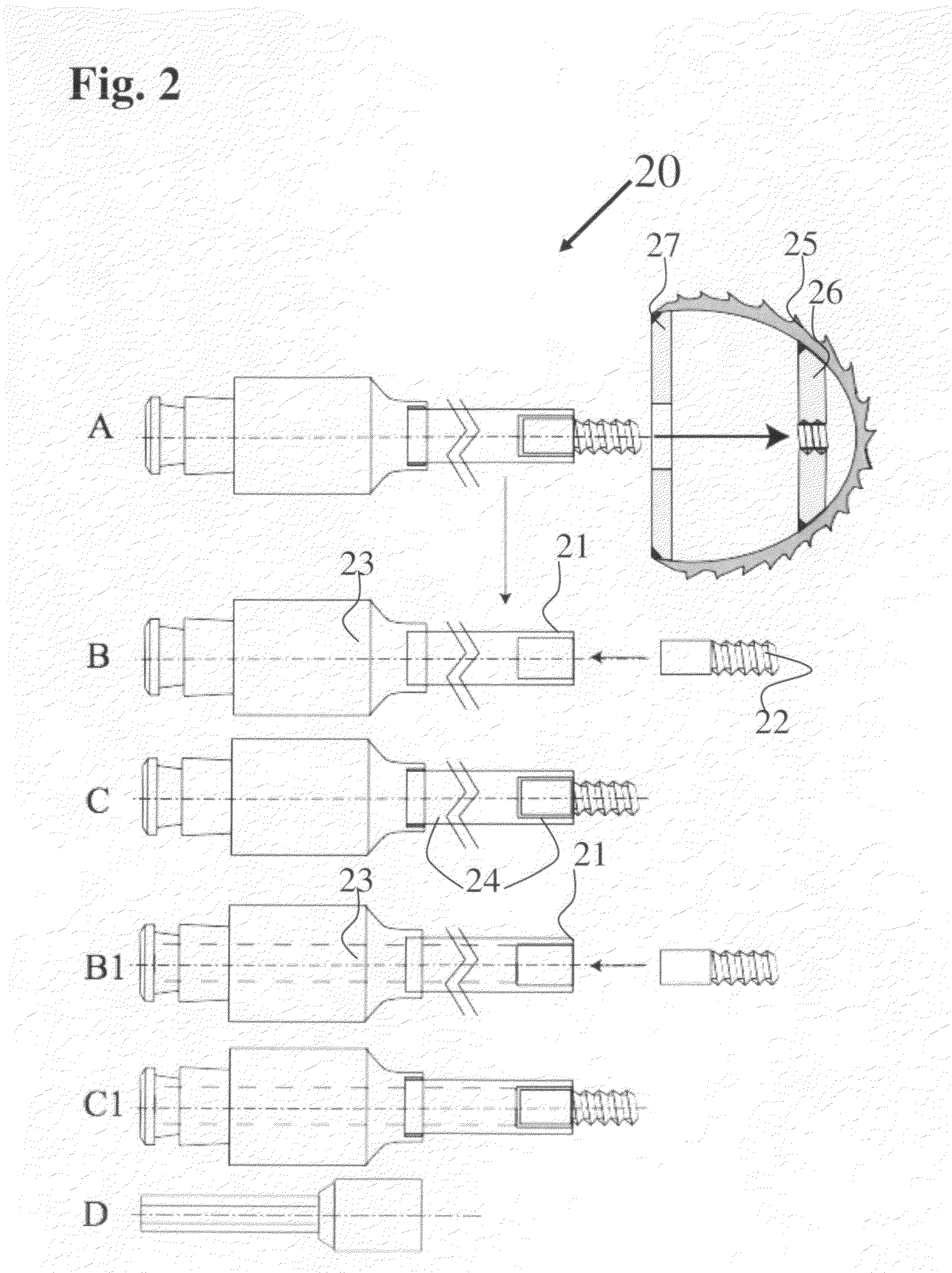
[0048]FIG. 2 Illustrates at 20 a cross sectional view depicting a disposable reamer shaft attached to one design of disposable modular spherical hollow reamer. The right side of the sub figure of FIG. 2 marked A depicts the manufactured disposable spherical hollow reamer. It has a cutting spherical shell 25 with a welded first plate at 26 having a threaded aperture and a second welded plate 27 with a central aperture. The drive shaft 21 for this disposable modular spherical hollow reamer is shown to be a solid rod in the sub figure of FIG. 2, marked B and as a tube in the sub figure of FIG. 2, marked B1 representing a cannulated disposable reamer shaft. In both cases, the right side of the rod or tube has a milled aperture to receive the modular hollow reamer attachment piece 22, which is glued by epoxy at 24. The other end of the rod or tube 21 is glued to a J&J drive chuck 23 also using epoxy glue at 24. Note that the J&J drive chuck 23 slides over the rod or tube 21 creating the ...

second embodiment

[0049]FIG. 3 Illustrates at 30 a cross sectional view depicting a disposable reamer shaft attached to one design of disposable modular spherical hollow reamer. The right side of the sub figure of FIG. 3, marked A depicts the manufactured disposable spherical hollow reamer. It has a cutting spherical shell 36 has a welded female screw thread at 37. The drive shaft 31 for this disposable modular spherical hollow reamer is shown to be a solid rod in the sub figure of FIG. 3, marked B and as a tube in the sub figure of FIG. 3, marked B1 representing a cannulated disposable reamer shaft. In both cases, the left side of the modular reamer attachment piece 32 has a milled aperture to receive right side of the rod or tube 31, which is glued by epoxy at 35. A tapered conical element 34 is also glued by epoxy to the shaft as shown at 35 and slides over the interior of the spherical dome of the reamer 36. The other end of the rod or tube 31 is glued to a J&J drive chuck 23 also using epoxy glu...

third embodiment

[0050]FIG. 4 Illustrates at 40 a cross sectional view depicting a disposable reamer shaft attached to a disposable modular tapered hollow reamer. The right side of the sub figure of FIG. 4, marked A depicts the assembled modular tapered hollow reamer with a finished shaft. The sub figure of FIG. 4, marked B depicts how the tapered hollow reamer is disassembled. The drive shaft 41 for this disposable modular tapered hollow reamer is shown to be a solid rod in the sub figure of FIG. 4, marked C and as a tube in the sub figure of FIG. 3, marked C1 representing a cannulated disposable reamer shaft. In both cases, the right side of rode or tube 41 has a milled aperture to receive the left side of the attachment piece 42, which is glued by epoxy at 45. A tapered conical element 44 is also glued by epoxy to the shaft as shown at 45 and contacts the interior of the tapered hollow reamer 46. The other end of the rod or tube 41 is glued to a J&J drive chuck 43 also using epoxy glue at 45. The...


PUM

PropertyMeasurementUnit
Lengthaaaaaaaaaa
Lengthaaaaaaaaaa
Diameteraaaaaaaaaa

Abstract

A low cost disposable reamer shaft is made from a rod or tube stock of stainless steel, Nitinol or fiber reinforced polymer having a precise outer diameter in the range of 4 to 14 millimeter and is cut to a shaft length of 250 to 400 millimeters. An attachment piece with male or female thread matching a spherical hollow or tapered hollow reamer is machined and glued with epoxy on one end of the rod of tube stock using a precision centerline aligning jig. An attachment piece for connecting to a drive power unit is machined and glued with epoxy to the other end of the rod or tube stock thus forming a low cost disposable reamer shaft that aligns the centerline of the shaft with that of the reamer. The shaft contacts the reamer at two attachment locations that are displaced from each other, providing precise centerline alignment.

Description

[0001]This is a Continuation-In-Part of application Ser. No. 12 / 0,722,671, filed on Feb. 27, 2008 for “Modular spherical hollow reamer assembly for medical applications ” which is a Continuation-In-Part of application Ser. No. 11 / 973,260, filed Oct. 5, 2007 for “Modular Tapered Hollow Reamer For Medical Applications” which, in turn, is a Continuation-In-Part of application Ser. No. 11 / 704,754, filed Feb. 9, 2007, the disclosures of which are hereby incorporated in their entirety by reference thereto.BACKGROUND OF THE INVENTION[0002]1. Field of the Invention[0003]The present invention relates to a disposable reamer shaft that may be attached to a modular disposable spherical or tapered hollow reamer, the disposable reamer shaft being concentrically attached to a modular hollow reamer to provide wobble free rotation of the reamer tool.[0004]2. Description of the Prior Art[0005]Reaming of the internal canal of bones is required in many surgical procedures of orthopedic surgery. These p...

Claims


Application Information

Patent Timeline
IPC IPC(8): A61B17/00B21K5/04
CPCA61B17/1617A61B17/1666A61B2017/0023Y10T29/49826
Inventor SIDEBOTHAM, CHRISTOPHER G.LEWIS, RANDALL J.ROITBURG, LEON
Owner LRS SCI & TECH LLC
Why Eureka
Try Eureka