Apparatus and methods for testing a fuel injector nozzle

a fuel injector and apparatus technology, applied in mechanical apparatus, machines/engines, instruments, etc., can solve the problems of increasing the frequency of soot emissions, the absolute accuracy of measuring the spray force, and the inability to meet the standard required of modern nozzle designs, so as to reduce vibration and minimise the static friction of the plunger within the bore

Inactive Publication Date: 2010-07-08
DELPHI TECH IP LTD
View PDF15 Cites 33 Cited by
  • Summary
  • Abstract
  • Description
  • Claims
  • Application Information

AI Technical Summary

Benefits of technology

[0040]The apparatus may include a main chamber within which the measurement chamber is located. The mounting means may be arranged such that the nozzle extends into the main chamber. The main chamber may be arranged to collect the fuel from the other spray hole outlets which is not directed into the measurement chamber. The main chamber may include an outlet for fuel. The outlet may be in fluid communication with a measurement system for quantifying the fuel collected in the main chamber. This enables the mass flow from the other spray hole outlets to be determined, thereby allowing the determination of the mass flow from an individual spray hole outlet relative to the total mass flow from the nozzle.
[0041]The apparatus may include a target mounted within the measurement chamber. The target may be connected to a sensor. The apparatus may be arranged such that the fuel spray from at least one spray hole outlet of the multi-hole nozzle is directed at the target, and the sensor may be calibrated to determine the spray force of the fuel spray impacting the target. Advantageously, the sensor may be located remotely from the target. By locating the sensor remotely from the target, the sensor is not subject to the vibrations of the apparatus and hence the sensor can output a substantially steady signal. Whereas the raw force signal from the Desantes technique described above and as shown in FIG. 1, tends to vary rapidly with time, the technique of the present invention does not suffer in this way. This allows measurements to be made to within the required degree of accuracy of 1%.
[0042]The sensor may be located outside the main chamber. In addition to reducing vibrations as described above, this arrangement provides for easy access to the sensor. The sensor may be connected to the target through a closed hydraulic circuit. The target may be mounted to a plunger which may be slidably received within a bore. The diametric clearance between the plunger and the bore is preferably within the range 0.5 to 4 microns, the bore thereby constricting the target to move in a substantially linear direction. The bore preferably extends substantially parallel to the measurement chamber axis of the measurement chamber, such that when the measurement chamber axis is aligned with the designed axis of the spray hole, only the substantially axial component of the spray force is measured. The bore may be connected to the sensor by a conduit containing hydraulic fluid. The plunger may be arranged to periodically rotate or oscillate within the bore, to minimise the static friction of the plunger within the bore.
[0043]The apparatus may provide for relative rotation between the nozzle and the measurement chamber. For example, the main chamber, including the measurement chamber, may be arranged for rotation about the vertical axis relative to the nozzle. Alternatively, the fuel injector in which the nozzle is mounted may be rotated relative to a substantially fixed main chamber. Further, the vertical position of the nozzle within the mounting may be varied. The apparatus may further comprise means for setting the needle lift of the nozzle needle, thereby enabling mass flow, spray force and momentum efficiency to be determined for each spray hole and at different needle lift settings.
[0044]It is important to allow the static ambient gas pressure in the measurement chamber to equalise with the static ambient gas pressure in the main chamber, otherwise any ambient pressure difference may affect the force sensor reading. This may be achieved by ensuring that the aperture in the measurement chamber is sized such that there is some additional clearance around the fuel spray / jet as it passes through the aperture. To further ensure that the ambient pressure is equalised between the main chamber and the measurement chamber, a vent may be placed in the main chamber. The vent may be located close to an annulus around the end of the nozzle stem such that the fuel jets draw a small flow of atmospheric air into the main chamber at low velocity, thereby preventing fuel mist escaping into the atmosphere. The measurement chamber may have a separate vent which also goes to atmosphere. This arrangement equalises the ambient pressures in the two chambers for accurate force sensor measurements with minimum escape of fuel mist to the atmosphere.

Problems solved by technology

However, there is a tendency for soot emissions to increase when high levels of EGR are employed.
The raw spray force signal from this technique tends to vary rapidly with time, owing partly to the turbulent structure of the impacting fuel spray and the vibration forces induced in the test rig from the dynamic operation of the injector.
Electronic frequency filtering can be used to give a smoother force signal, but the absolute accuracy of measuring the spray force, and hence spray momentum, does not meet the standard required of modern nozzle designs which must be measurable to an accuracy of at least one percent.
Although the nozzle discharge coefficient Cd is useful when calibrating a fuel injection system to deliver the correct quantity of injected fuel, it does not directly quantify the momentum of the fuel spray, and hence the emissions performance of the nozzle.
Further, it can be difficult to measure the nozzle diameter or spray hole area A, particularly with certain shapes of spray hole nozzle such as convergent spray holes which are often used in advanced nozzle designs.
However, optical techniques can present problems because the edges of the fuel spray / jet are often indistinct, which makes measuring the direction of the fuel spray to a sufficient degree of accuracy difficult.
For example, if the initial included angle is too large, the fuel spray / jet will expand and entrain the air charge in the combustion chamber too rapidly, and hence decelerate too rapidly.
The result of this is that the fuel spray / jet does not penetrate far enough into the combustion chamber.
This under-penetration means that the fuel spray / jet does not utilise the air available in the outer radii of the combustion chamber, thereby causing higher exhaust emissions.
Conversely, if the initial included angle is too small, the fuel spray / jet will penetrate too far into the combustion chamber before it expands in width sufficiently to entrain the air charge.
This over-penetration may result in liquid fuel being deposited on the walls of the combustion chamber, thereby causing unburnt hydrocarbon emissions.
However, optical techniques also present problems for measuring the included angle to a sufficient degree of accuracy because of the indistinct edges of the fuel spray / jet.

Method used


Image

  • Apparatus and methods for testing a fuel injector nozzle
  • Apparatus and methods for testing a fuel injector nozzle
  • Apparatus and methods for testing a fuel injector nozzle

Examples


Embodiment Construction

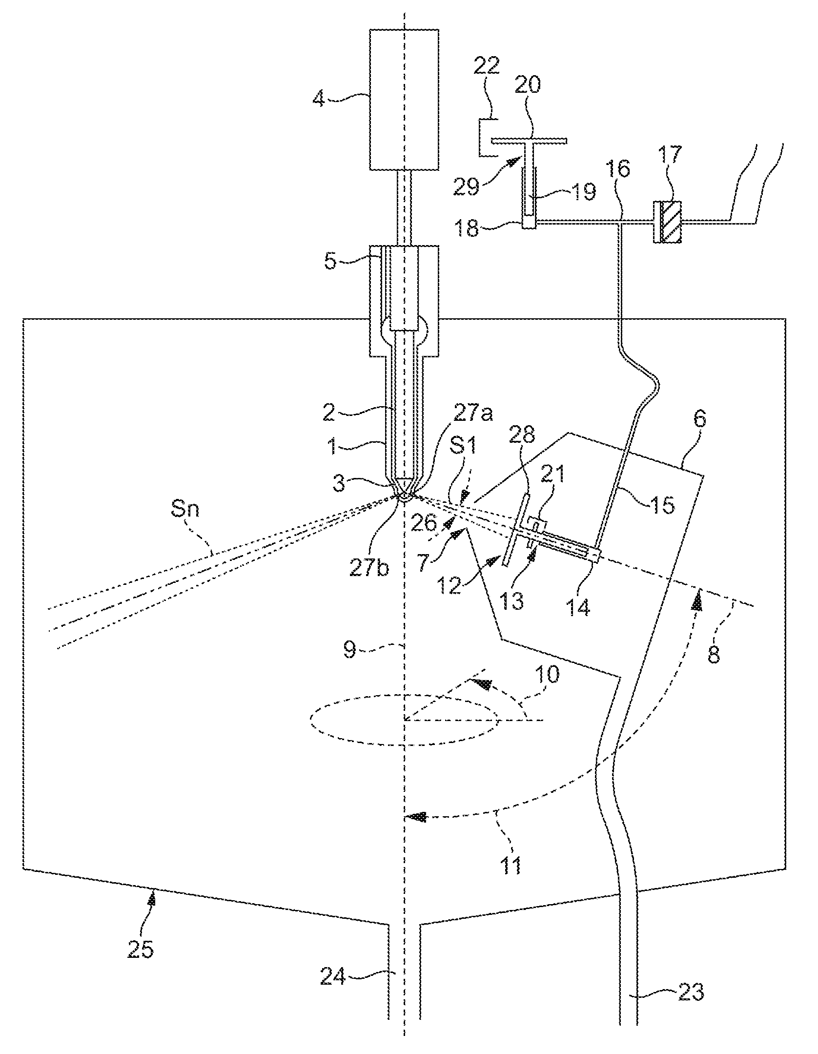
[0062]Referring to FIG. 4, a section through a test rig of an embodiment of the invention is shown schematically. A sample multi-hole fuel injector nozzle 1 is shown mounted on the test rig. The fuel injector nozzle 1 is mounted within a fuel injector body (not shown in FIG. 4), and extends into a main chamber 25. Fuel is supplied to the nozzle 1 via an inlet drilling 5 in the nozzle 1. An electronic control valve (not shown in FIG. 4) is provided for controlling fuel flow to the nozzle 1.

[0063]A plurality of spray hole outlets are defined in the nozzle 1, of which a first spray hole outlet 27a and a second spray hole outlet 27b are indicated in FIG. 4. The nozzle 1 comprises a nozzle needle 2, which is moveable relative to a needle seat 3 for controlling fuel flow through the spray hole outlets 27a, 27b. The spray hole outlets 27a, 27b are closed by the nozzle needle 2 when the nozzle needle 2 is seated, such that fuel flow through the spray hole outlets 27a, 27b is prevented. An i...


PUM


Abstract

An apparatus and method is described for testing a multi-hole fuel injector nozzle. The apparatus comprises mounting means for the multi-hole nozzle and fuel supply means for supplying fuel to the multi-hole nozzle. The multi-hole nozzle is mounted outside a measurement chamber for capturing the fuel spray from an individual spray hole outlet of the multi-hole nozzle. In one embodiment, the apparatus includes a spray target plate, located within the measurement chamber, at which the fuel spray is directed. The spray target plate (28) is connected to a remote pressure sensor, which is used to determine the spray force of the fuel spray acting on the spray target plate. The apparatus is further arranged to determine the mass flow rate of the fuel spray. A new parameter, referred to as ‘momentum efficiency’ is defined, and calculated using the determined values of spray force and mass flow rate.

Description

TECHNICAL FIELD[0001]The present invention relates to an apparatus for analysing a fuel injector nozzle of an internal combustion engine, such as a diesel engine, and to methods of testing a fuel injector nozzle using the apparatus. More specifically, the invention provides a test rig, and associated techniques, for analysing the fuel spray from the individual spray holes of a fuel injector nozzle, thereby to determine various parameters of the nozzle to a high degree of accuracy.BACKGROUND[0002]It is desirable to reduce harmful emissions from diesel engine exhaust, to minimise the impact on the environment, and to comply with increasingly stringent emission regulations.[0003]Many modern diesel engines employ exhaust gas re-circulation (EGR) for reducing harmful NOx emissions. However, there is a tendency for soot emissions to increase when high levels of EGR are employed. It is known that soot emissions from diesel engine exhaust can be reduced by providing high rates of air / fuel m...

Claims


Application Information

Patent Timeline
Patent Type & Authority Applications(United States)
IPC IPC(8): G01M15/04
CPCF02M65/001
Inventor GREEVES, GODFREY
Owner DELPHI TECH IP LTD
Why Eureka
Try Eureka