Micromechanical slow acting valve system

a technology of slow-acting valve and micro-mechanical body, which is applied in the direction of valve details, operating means/release devices of valves, engine components, etc., to achieve the effects of low power consumption, high flow rate and large cross-sectional flow area

Inactive Publication Date: 2010-07-08
AAC MICROTEC
View PDF23 Cites 7 Cited by
  • Summary
  • Abstract
  • Description
  • Claims
  • Application Information

AI Technical Summary

Benefits of technology

[0014]It is a further advantage of the invention to provide an integrated microvalve system that has a large cross-sectional flow area permitting a high flow rate in one or several parallel branches. The microvalve system may comprise several parallel fluid branches, each having different pre-defined response times.
[0015]It is yet a further advantage of the invention to provide an integrated microvalve system with low power consumption.
[0016]It is yet another advantage of the invention to provide a microvalve that comprises a protection for catastrophic failure due to exposure to high pressure.
[0017]Embodiments of the invention are defined in the dependent claims. Other objects, advantages and novel features of the invention will become apparent from the following

Problems solved by technology

Obviously the prior art has drawbacks with regards to being able to provide valve system having small size and weight and permitting high flow rates and a pre-determined response time.

Method used


Image

  • Micromechanical slow acting valve system
  • Micromechanical slow acting valve system
  • Micromechanical slow acting valve system

Examples


Embodiment Construction

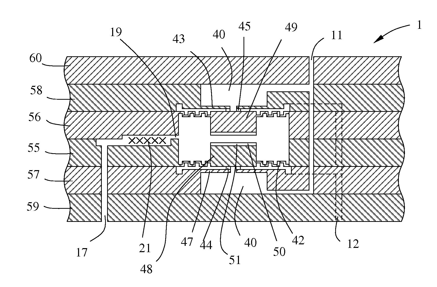
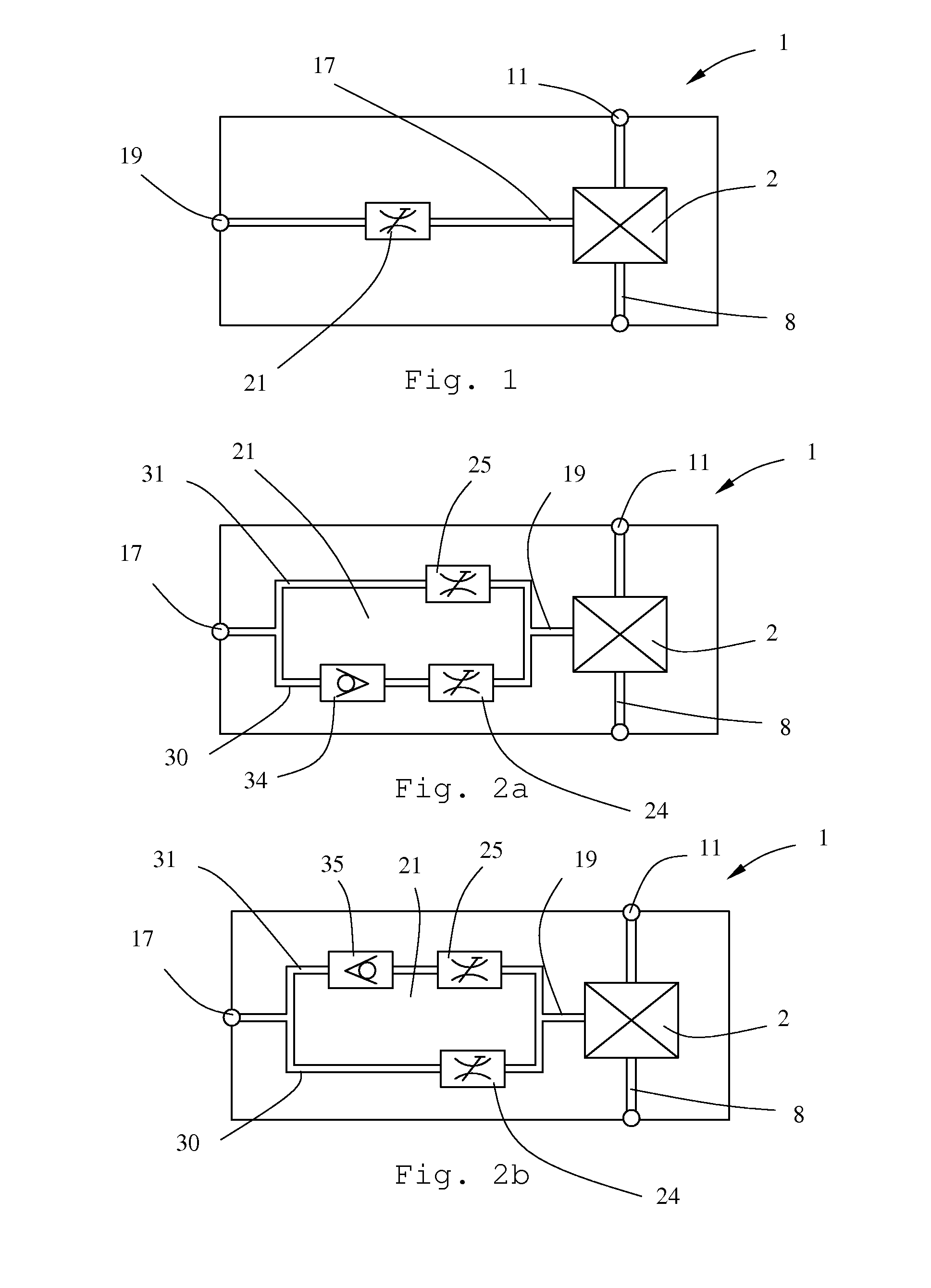
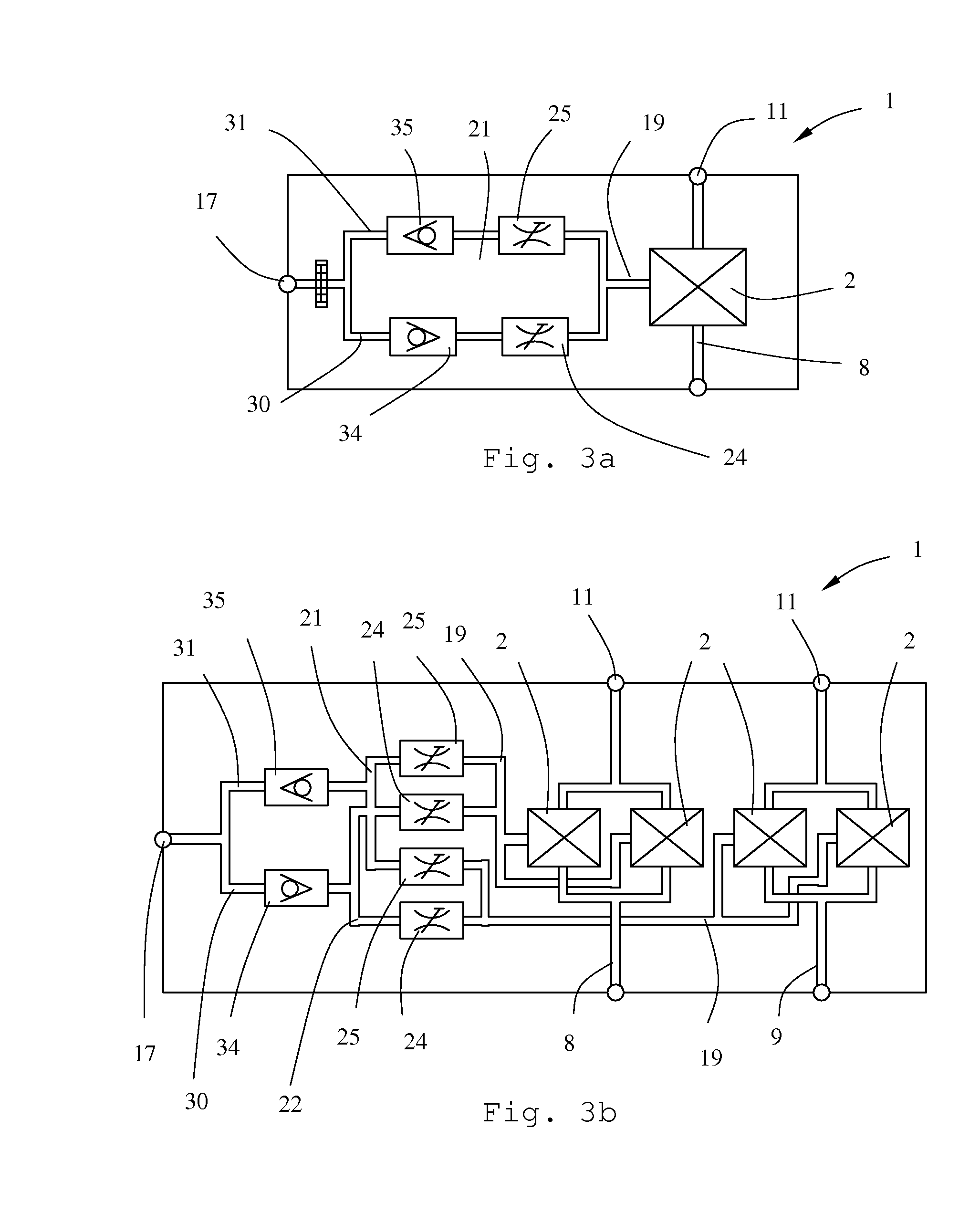
[0028]The basis of the present invention is control of the turn-on and / or turn-off response times of at least one microvalve in an integrated microvalve system. The integrated microvalve system is preferably designed and manufactured using methods, materials and technologies of the field of Microsystem Technology (MST) or Microelectromechanical Systems (MEMS).

[0029]Commonly microsystems for fluidics are built using silicon micromachining, which may comprise shaping, typically using photolithography and etching, and bonding of silicon wafers. The present invention is however not limited to silicon micromachining. By way of example other semiconductor materials, polymers and ceramics may be used. Neither is the present invention limited to systems built using photolithography and etching, for example may high precision machining, laser machining, injection moulding, etc. be used. Micromachined wafers may be joined using other methods than bonding, such as welding, soldering, gluing, e...


PUM


Abstract

The present invention provides an integrated microvalve system (1) comprising at least a first fluid branch (8) and a microvalve (2) being controlled by a control pressure in a control channel (17). The microvalve (2) is adapted to control a fluid flow in the first fluid branch (8). A flow restrictor arrangement (21) is located between a control port (19) and the control channel (17) to give a pre-determined turn-on and turn-off response characteristics of the microvalve (2). Preferably the flow restrictor arrangement (21) comprises a deflate channel (30) and an inflate channel (31) arranged in parallel. Each channel (30, 31) comprises a check valve (34, 35) and a flow restrictor (24, 25), which may have different flow restriction to give different turn-on and turn-off response characteristics for the microvalve (2).

Description

TECHNICAL FIELD OF THE INVENTION[0001]The present invention relates to miniaturised valve systems, and in particular to integrated valve systems, which commonly are fabricated using silicon micromachining.BACKGROUND OF THE INVENTION[0002]Microsystems technology (MST) or microelectromechanical systems (MEMS) can be regarded as a spin-off from the microelectronics. In miniaturised systems from this technology field, integrated circuits may be combined with e.g. mechanical, fluid, chemical, or biological systems in an integrated system. Commonly the choice of design, materials and processing is made on the basis of the vast knowledge from microelectronic processing, but as the field of MEMS has developed and found new application areas the technology have been acknowledged as a stand-alone technology and the development of design and processing is rapidly improving.[0003]One important application area of MEMS is microfluidics. Microfluidics deals with the behavior, precise control and ...

Claims


Application Information

Patent Timeline
Patent Type & Authority Applications(United States)
IPC IPC(8): F16K31/165
CPCF16K99/0001F16K99/0005F16K2099/0084F16K2099/0074F16K2099/0076F16K99/0059
Inventor STENMARK, LARS
Owner AAC MICROTEC
Why Eureka
Try Eureka