Maglev motor and pump

a technology of maglev motor and pump, which is applied in the direction of positive displacement liquid engine, piston pump, liquid fuel engine, etc., can solve the problems of difficult assembly, inlet and outlet structure of the pump, intake and discharge loss increase, etc., to simplify the active control system of the magnetic bearing, simplify the structure, and reduce the effect of rotation loss of the rotor

Active Publication Date: 2010-07-08
IWAKI
View PDF15 Cites 14 Cited by
  • Summary
  • Abstract
  • Description
  • Claims
  • Application Information

AI Technical Summary

Benefits of technology

[0015]In addition, the maglev motor can be applied to a pump. According to the present invention, powerful magnetic bearing force can be generated by a simple structure, the rotation loss of a rotor can be reduced by suppressing the generati...

Problems solved by technology

However, when the patent document 1 is applied to a pump etc., the projected poles for controlling the position in the axis direction on both end surfaces of a rotor complicate the structure of the inlet and the outlet of the pump, and causes difficult assembly.
Furthermore, since the path of a liquid is complicated, intake and discharge losses increase.
In addition, since the patent document 1 provides the magnetic bearings at the upper and lower portions of the rotor to susp...

Method used


Image

  • Maglev motor and pump
  • Maglev motor and pump
  • Maglev motor and pump

Examples


embodiment 1

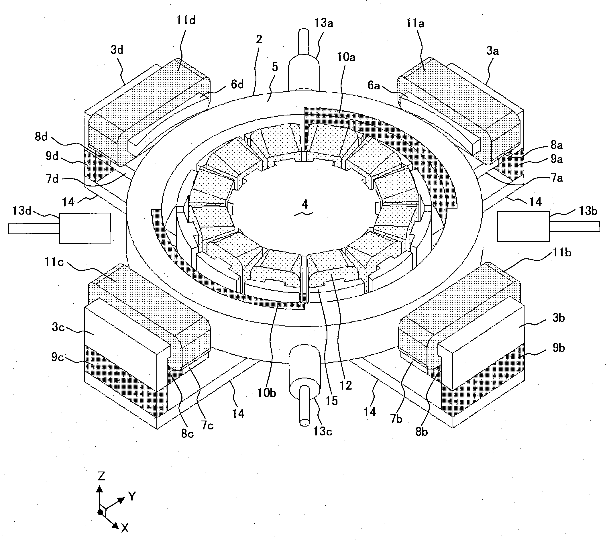
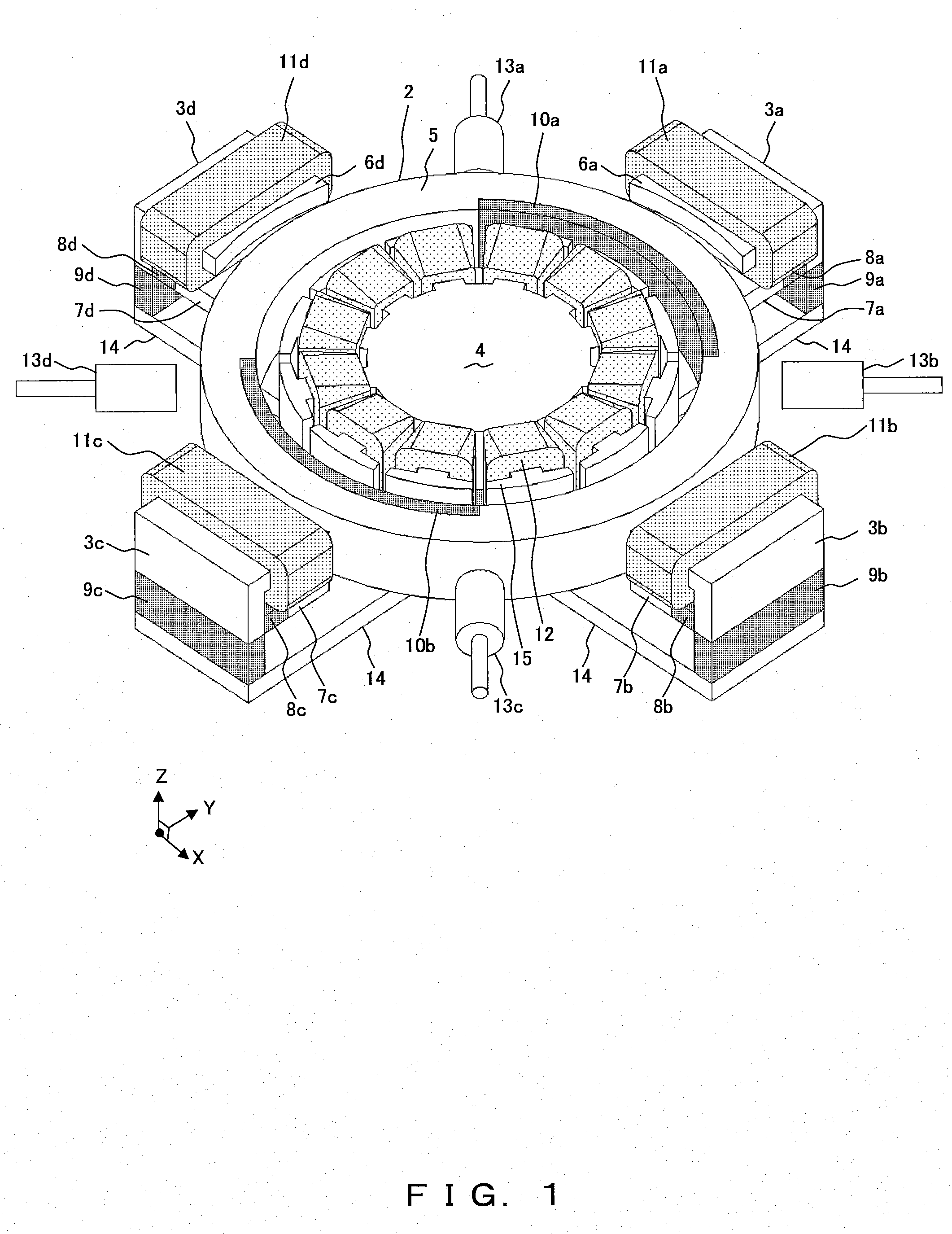
[0027]FIG. 1 shows an embodiment of the present invention. A stator 1 of the maglev motor is configured by a magnetic bearing unit provided outside a rotor 2 (donut-shaped) and a motor unit provided inside the rotor 2.

[0028]The magnetic bearing unit is configured by magnetic bearing yokes 3 (3a through 3d), a bridge yoke 14, magnetic bearing coils 11 (11a through 11d), first permanent magnets 8 (8a through 8d), and second permanent magnets 9 (9a through 9d).

[0029]First projected poles 6 (6a through 6d) of the magnetic bearing yokes 3 (3a through 3d) have magnetic bearing coils 11 (11a through 11d) close-wound around the respective projected poles.

[0030]Second projected poles 7 (7a through 7d) of the magnetic bearing yokes 3 (3a through 3d) are arranged opposite the first projected poles 6 (6a through 6d) substantially parallel to the axial direction, and has the first permanent magnets 8 (8a through 8d). An electromagnet is configured by each first projected pole 6 and each second p...


PUM


Abstract

A maglev motor and a pump using the maglev motor can be provided with strong magnetic bearing force generated by a simple structure, rotation losses of a rotor reduced with the generation of an eddy current suppressed, and a configuration of magnetic bearing can downsize by using a thin rotor. The donut-shaped rotor is arranged between the magnetic bearing unit and the motor unit, the motor yoke of the motor radially has a plurality of projected poles, a coil is close-wound around the projected pole, predetermined clearance is made between the inner side of the rotor and the projected pole, a plurality of two projected poles opposite each other near either end portions of the outer side of the rotor are provided circularly at equal intervals on the magnetic bearing yoke of the magnetic bearing unit, a magnetic bearing coil is close-wound around one of the two projected poles, a first permanent magnet is provided for the other projected pole, predetermined clearance is made on one side of the rotor end portion and the bridge unit for connecting the magnetic bearing unit to the motor unit is provided, a second permanent magnet is provided between the projected pole provided for the magnetic bearing yoke and the bridge yoke of the bridge unit, a third permanent magnet is provided between the motor yoke and the bridge yoke, a plurality of motor permanent magnets opposite the motor yoke are provided inside the rotor, and all projected poles provided on the bridge unit side of the magnetic bearing unit can be close-wound by the magnetic bearing coil, or provided with the first permanent magnet.

Description

TECHNICAL FIELD[0001]The present invention relates to the structure and control of a maglev motor, and more specifically to the technology of a hybrid maglev motor in a double bias permanent magnetic system.BACKGROUND ART[0002]Recently, a hybrid maglev motor in a double bias permanent magnetic system has been proposed as a maglev motor.[0003]A 5-axis-controlled hybrid magnetic bearing according to the patent document 1 realizes magnetic levitation and rotation on a long axis rotor for forming a pump impeller etc. by efficient 5-axis control using a permanent magnet for generating a bias magnetic flux. By devising a magnetic path of the bias magnetic flux, magnetic suspending force higher than that of a magnetic levitation system using only an electromagnet can be generated.[0004]According to the patent document 2, a double bias magnetic bearing (magnetic suspension control) can generate further magnetic suspending force by providing a plurality of bias magnets for a conventional hyb...

Claims


Application Information

Patent Timeline
IPC IPC(8): F04B17/03H02K7/09
CPCF04D13/06F04D29/048H02K7/14F16C32/048H02K7/09F16C32/0465F16C2360/44F16C32/04H02K21/16H02K29/06
Inventor ONUMA, HIROYUKI
Owner IWAKI
Why Eureka
Try Eureka