System and Method for Highly Attenuating Material Artifact Reduction in X-Ray Computed Tomography

a computed tomography and high-attenuation technology, applied in tomography, image enhancement, instruments, etc., can solve the problems of severe image artifacts, obscuring anatomical structures, and affecting entire images, etc., and achieve the effect of suppressing artifacts

Active Publication Date: 2010-07-22
MAYO FOUND FOR MEDICAL EDUCATION & RES
View PDF16 Cites 44 Cited by
  • Summary
  • Abstract
  • Description
  • Claims
  • Application Information

AI Technical Summary

Problems solved by technology

Metal implants are not uncommon in subjects receiving CT examinations and may produce severe image artifacts in the form of bright and dark streaks and dark shadows.
Small metal objects that occupy only a small image region can produce artifacts that affect entire images, obscuring anatomical structures and significantly degrading diagnostic value.
Metal artifacts arise from the data inconsistency between ideal models assumed by reconstruction algorithms and the actual CT signal, which has been contaminated by the metal, or other highly attenuating material.
X-rays are highly attenuated by metals and other materials, which in turn amplifies factors that lead to data inconsistencies and, eventually, artifacts such as noise, beam hardening, scattering, and non-linear partial volume effects.
Noise in projection data may be reduced by increasing the tube output (“mAs”) of the x-ray source; however, such an approach delivers an increased radiation dose to a subject and does not correct for other data inconsistencies, including those that lead to streaking and shading artifacts.
While this method is common in scan protocols for subjects having metal implants, it offers minimal improvement in scan quality over scans performed using standard tube potentials.
Adaptive filtering may be used to reduce streaking artifacts caused by photon starvation by adaptively smoothing projection data based on noise level; however, this method cannot correct the severe data inconsistencies caused by highly attenuating materials, such as metals, for example, titanium, cobalt, and stainless steel.
While promising, these methods are difficult to implement with the standard reconstruction algorithms in modern CT scanners and can be too computationally expensive for the large data sets generated by multi-slice CT scanners.
However, severe artifacts in the initial reconstructed images often preclude accurate metal segmentation and prevent effective artifact reduction.
Furthermore, reprojection of the metal image to projection space is computationally expensive, especially for the large clinical datasets acquired with multi-slice helical CT, and is sometimes prevented by the unavailability of sufficient information regarding the data acquisition geometry.
Such approaches work well for simple data acquisition geometries and simple metal shapes, but these approaches cannot provide effective metal artifact reduction when using complicated data acquisition geometries, for example, multi-slice helical CT, or when imaging complicated metal shapes or anatomical features.
The direct segmentation of metal in projection views acquired using multi-slice helical CT, which are typically composed of matrices having a small longitudinal dimension (for example, 16-64 pixels for typical 16 or 64 slice scanners), is difficult for two primary reasons.
First, large quantities of projection data are often acquired to cover a long helical scanning range.
Therefore, most projections contain little or no metal content, decreasing a segmentation algorithm's ability to assess the metal content of a projection and segment metal consistently among all projections.
Second, the large amount of data acquired during multi-slice helical CT scans, for example, 40,000-60,000 projection views for a typical chest-abdomen-pelvis scan, makes it extremely difficult for a human to review and control the segmentation process.

Method used


Image

  • System and Method for Highly Attenuating Material Artifact Reduction in X-Ray Computed Tomography
  • System and Method for Highly Attenuating Material Artifact Reduction in X-Ray Computed Tomography
  • System and Method for Highly Attenuating Material Artifact Reduction in X-Ray Computed Tomography

Examples


Embodiment Construction

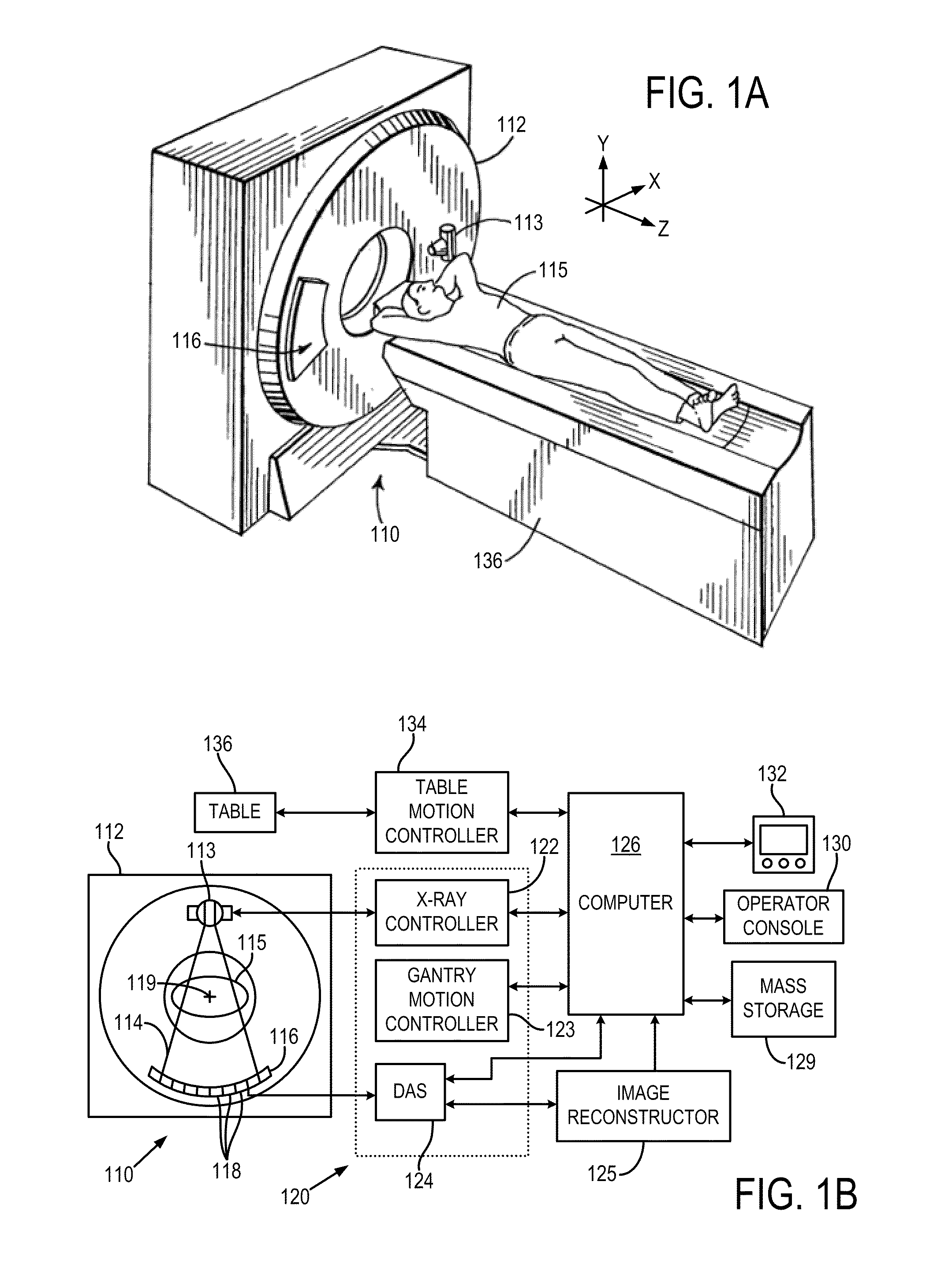
[0034]With initial reference to FIGS. 1A and 1B, an x-ray computed tomography (“CT”) imaging system 110 includes a gantry 112 representative of a “third generation” CT scanner. Gantry 112 has an x-ray source 113 that projects a fan-beam, or cone-beam, of x-rays 114 toward a detector array 116 on the opposite side of the gantry. The detector array 116 is formed by a number of detector elements 118 which together sense the projected x-rays that pass through a medical patient 115. Each detector element 118 produces an electrical signal that represents the intensity of an impinging x-ray beam and hence the attenuation of the beam as it passes through the patient. During a scan to acquire x-ray projection data, the gantry 112 and the components mounted thereon rotate about a center of rotation 119 located within the patient 115.

[0035]The rotation of the gantry and the operation of the x-ray source 113 are governed by a control mechanism 120 of the CT system. The control mechanism 120 inc...


PUM


Abstract

The present invention is a method for reducing artifacts caused by highly attenuating materials in x-ray computed tomography (“CT”) images. The method includes combining projection views acquired at equivalent view angles to generate a projection plane data set, from which a reformatted projection is produced. The reformatted projection is then processed to detect and segment regions corresponding to objects composed of metals, metal alloys, or other highly attenuating materials. These segmented regions are then removed from the reformatted projection and the removed portions replaced by attenuation information interpolated from portions of the reformatted projection adjacent the removed portions. The interpolated reformatted projection is then mapped back to a projection plane data set, and an image of the subject is reconstructed from the projection views contained in that data set. The reconstructed image, therefore, is one in which artifacts caused by highly attenuating materials are substantially suppressed.

Description

CROSS-REFERENCE TO RELATED APPLICATIONS[0001]This application claims the benefit of, and incorporates herein by reference in its entirety, U.S. Provisional Patent Application Ser. No. 61 / 145,924 filed on Jan. 20, 2009, and entitled “System and Method for Metal Artifact Reduction in Computed Tomography.”BACKGROUND OF THE INVENTION[0002]The present invention relates to x-ray computed tomography (“CT”) imaging systems and, more particularly, to a method for reducing artifacts resulting from highly attenuating materials in multi-slice helical CT.[0003]In a computed tomography system, an x-ray source projects a fan-shaped beam which is collimated to lie within an X-Y plane of a Cartesian coordinate system, termed the “imaging plane.” The x-ray beam passes through the object being imaged, such as a medical patient, and impinges upon an array of radiation detectors. The intensity of the transmitted radiation is dependent upon the attenuation of the x-ray beam by the object and each detecto...

Claims


Application Information

Patent Timeline
Patent Type & Authority Applications(United States)
IPC IPC(8): G06K9/00H05G1/60
CPCA61B6/032A61B6/12G06T11/005G06T2207/10081G06T2207/20036G06T5/005G06T2207/30004A61B6/027A61B6/5258G06T7/13
Inventor MCCOLLOUGH, CYNTHIA H.YU, LIFENG
Owner MAYO FOUND FOR MEDICAL EDUCATION & RES
Why Eureka
Try Eureka