Internal combustion engine exhaust gas control apparatus and control method thereof

a technology of exhaust gas control apparatus and control method, which is applied in mechanical apparatus, electric control, machines/engines, etc., can solve the problems of limiting the degree of freedom in design and complex structure of exhaust passage, and achieve the effect of not complicating the structure of exhaust passag

Inactive Publication Date: 2010-07-29
TOYOTA JIDOSHA KK
View PDF12 Cites 13 Cited by
  • Summary
  • Abstract
  • Description
  • Claims
  • Application Information

AI Technical Summary

Benefits of technology

[0008]This invention thus provides an internal combustion engine exhaust gas control apparatus, as well as a control method thereof, which is able to estimate th

Problems solved by technology

This makes the structure of the exhaust passage c

Method used


Image

  • Internal combustion engine exhaust gas control apparatus and control method thereof
  • Internal combustion engine exhaust gas control apparatus and control method thereof
  • Internal combustion engine exhaust gas control apparatus and control method thereof

Examples


Embodiment Construction

[0051]Hereinafter, example embodiments of the invention will be described in detail with reference to the accompanying drawings.

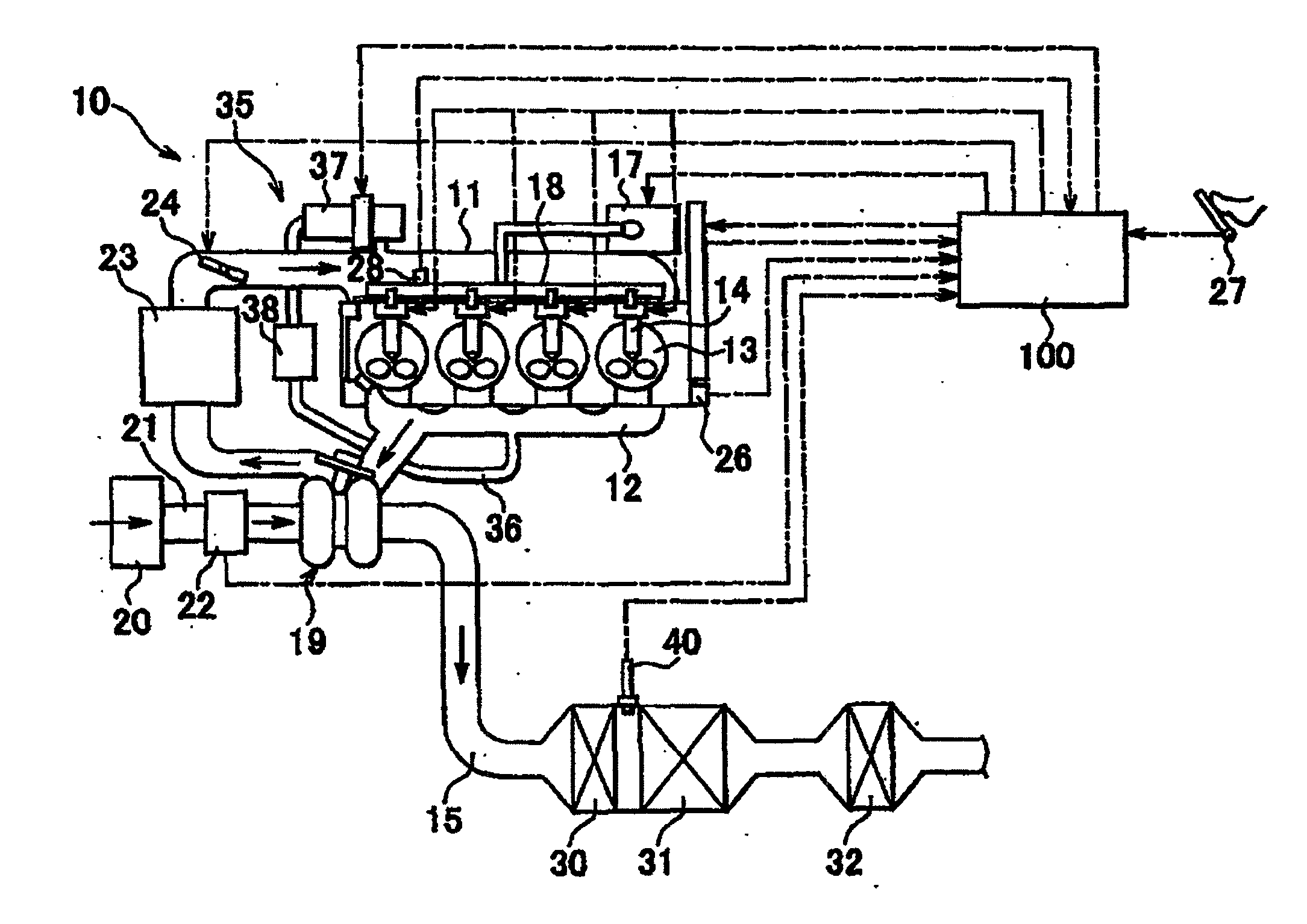
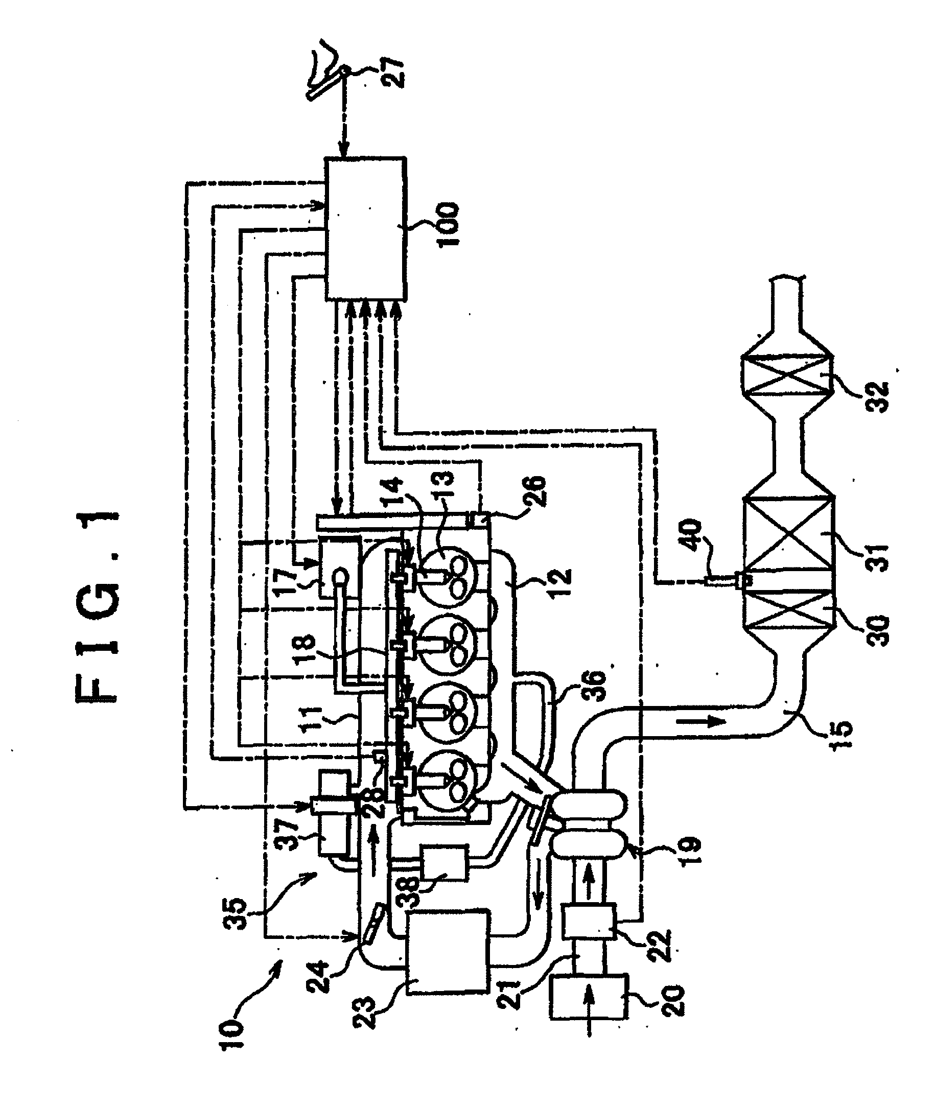
[0052]FIG. 1 is a system view schematically showing an internal combustion engine according to an example embodiment of the invention. As shown in the drawing, a vehicular compression ignition internal combustion engine, i.e., a diesel engine, (hereinafter also simply referred to as “engine”) 10 includes an intake manifold 11 that is communicated with an intake port, an exhaust manifold 12 that is communicated with an exhaust port, and a combustion chamber 13. In this example embodiment, fuel supplied from a fuel tank, not shown, to a high pressure pump 17 is fed under pressure by the high pressure pump 17 to a common rail 18 where it is accumulated. The high pressure fuel in the common rail 18 is then directly injected into the combustion chamber 13 from an injector (i.e., fuel injection valve) 14. Exhaust gas produced by the engine 10 flows from the exhau...


PUM


Abstract

An exhaust gas control apparatus includes a PM trapping filter provided in an exhaust gas passage of an internal combustion engine, an oxygen concentration sensor provided upstream of the filter, a device that estimates the air-fuel ratio of exhaust gas supplied to the oxygen concentration sensor, and a device that estimates the amount of PM trapped in the filter based on the estimated exhaust gas air-fuel ratio and the oxygen concentration sensor output. The amount of PM trapped in the filter is estimated using the fact that the oxygen concentration sensor output value changes according to the exhaust gas air-fuel ratio and the amount of PM accumulated on the oxygen concentration sensor. As a result, the structure of the exhaust passage is able to be kept simple because only an oxygen concentration sensor is added upstream of the filter.

Description

BACKGROUND OF THE INVENTION[0001]1. Field of the Invention[0002]The invention relates to an internal combustion engine exhaust gas control apparatus and a control method thereof. More particularly, the invention relates to technology for purifying particulate matter in exhaust gas.[0003]2. Description of the Related Art[0004]It is desirable to purify harmful gas components in exhaust gas produced by internal combustion engines used in automobiles and the like. More specifically, there is a need to purify particulate matter (hereinafter also referred to as “PM”) such as soot and soluble organic fraction (SOF) in exhaust gas produced by compression ignition internal combustion engines, i.e., diesel engines. One technology for purifying such particulate matter includes providing a filter in an exhaust passage of an engine and trapping the PM in the exhaust gas with this filter. This filter is typically referred to as a particulate filter, of more specifically in the case of a diesel en...

Claims


Application Information

Patent Timeline
IPC IPC(8): F01N3/01F01N11/00F01N3/10F01N9/00
CPCF01N3/0842F01N9/002F01N2560/025F01N2560/14F01N2560/20F02D41/029F02D41/1441F02D41/1458F02D2200/0812Y02T10/47F01N13/0097F01N13/009Y02T10/40
Inventor SHIBATA, DAISUKEIMAMURA, SHINICHIRO
Owner TOYOTA JIDOSHA KK
Why Eureka
Try Eureka