Machine tool and controlling method thereof

a technology of a machine tool and a controlling method, which is applied in the direction of program control, electric programme control, instruments, etc., can solve the problem of not reaching the predetermined removal volume, and achieve the effect of high accuracy and speed

Inactive Publication Date: 2010-07-29
JTEKT CORP
View PDF5 Cites 14 Cited by
  • Summary
  • Abstract
  • Description
  • Claims
  • Application Information

AI Technical Summary

Benefits of technology

[0016]The servo driver in the present invention executes in the second feedback control until the tool contacts with the workpiece. Then, the servo driver executes in the first feedback control after the tool contacted the workpiece. Thereby, the servo driver drives the servo motor at a time when the second feedback control can be executed, so that the movement of the tool controlled in the se

Problems solved by technology

In the feedback control, the bigger the gain value of the position control is, the sooner the reaching time to the final diameter in a risk of overshooting beyond the target to undercut the workpiec

Method used


Image

  • Machine tool and controlling method thereof
  • Machine tool and controlling method thereof
  • Machine tool and controlling method thereof

Examples


first embodiment

of the Present Invention

Mechanical Construction of the Grinding Machine

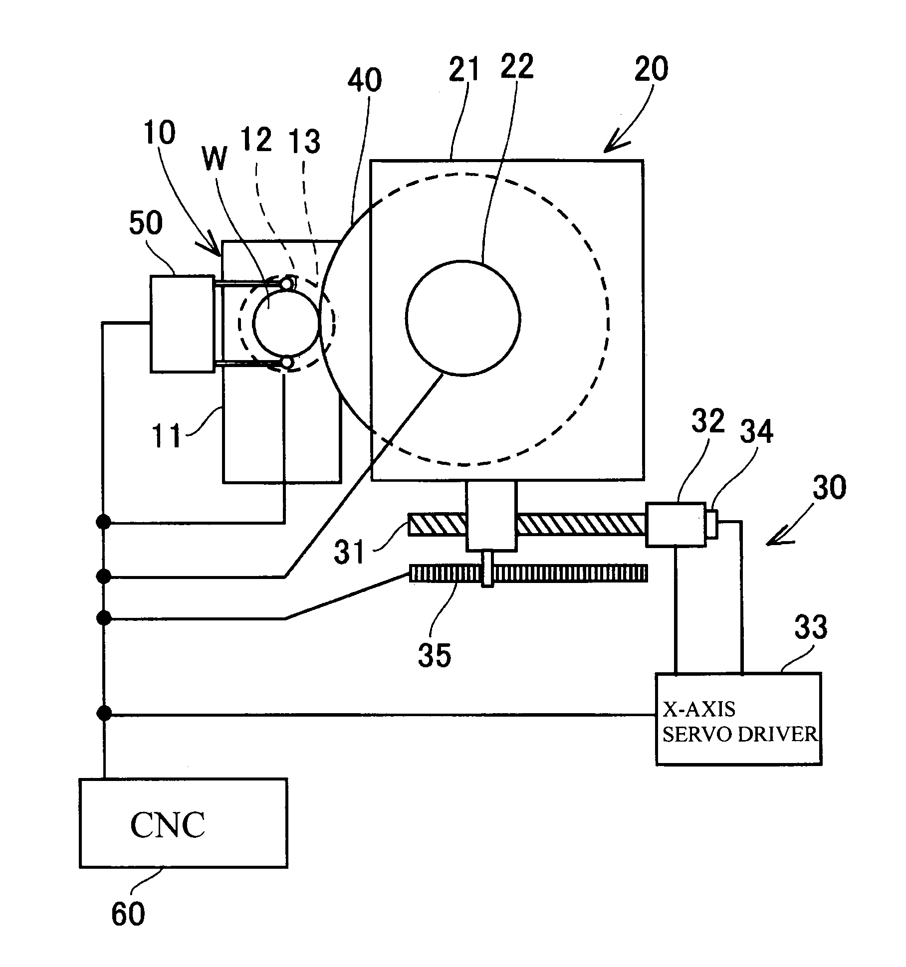
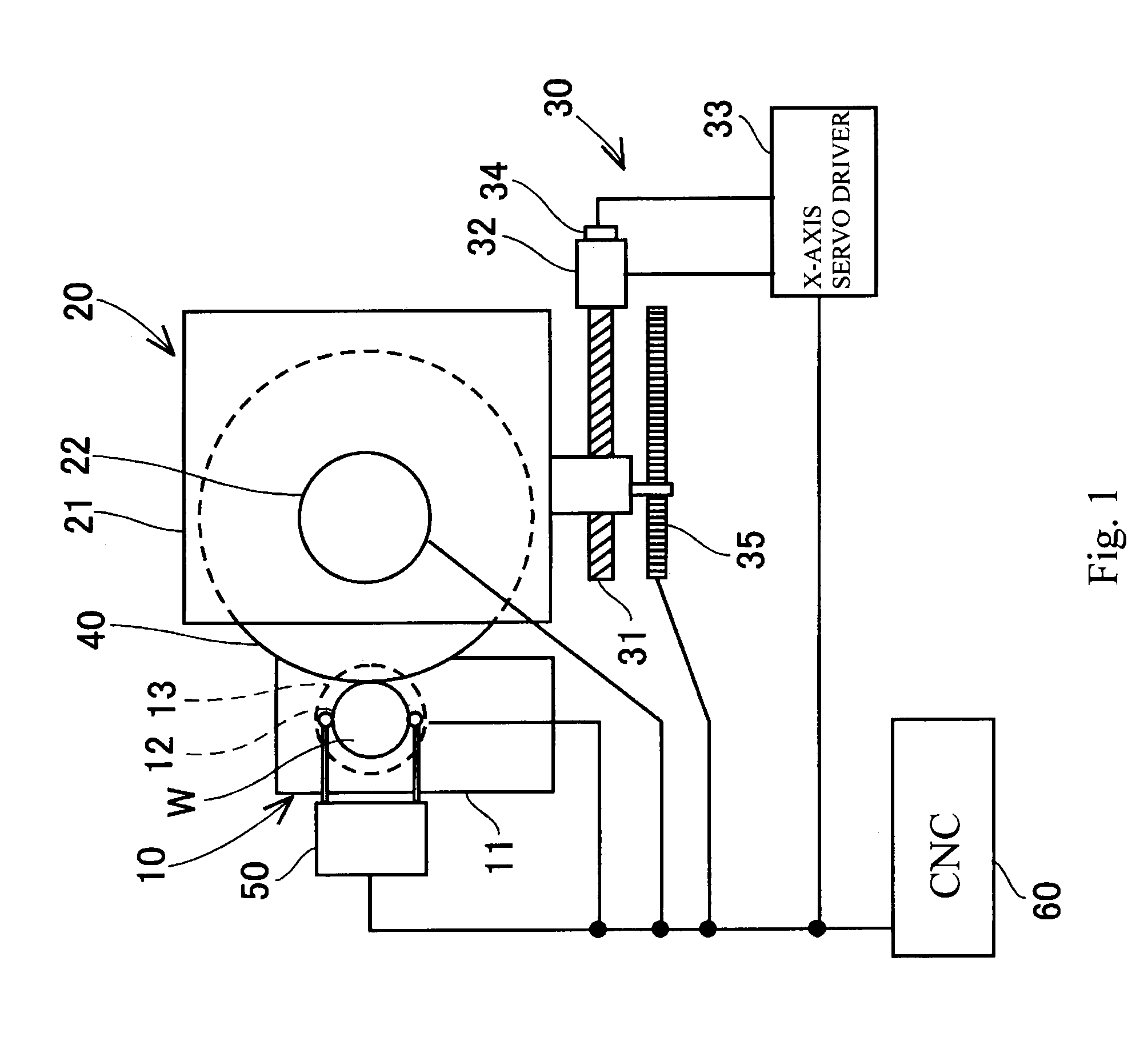
[0029]The machine construction of the grinding machine of the first embodiment according to the present invention is explained herein referred to FIG. 1 and FIG. 2.

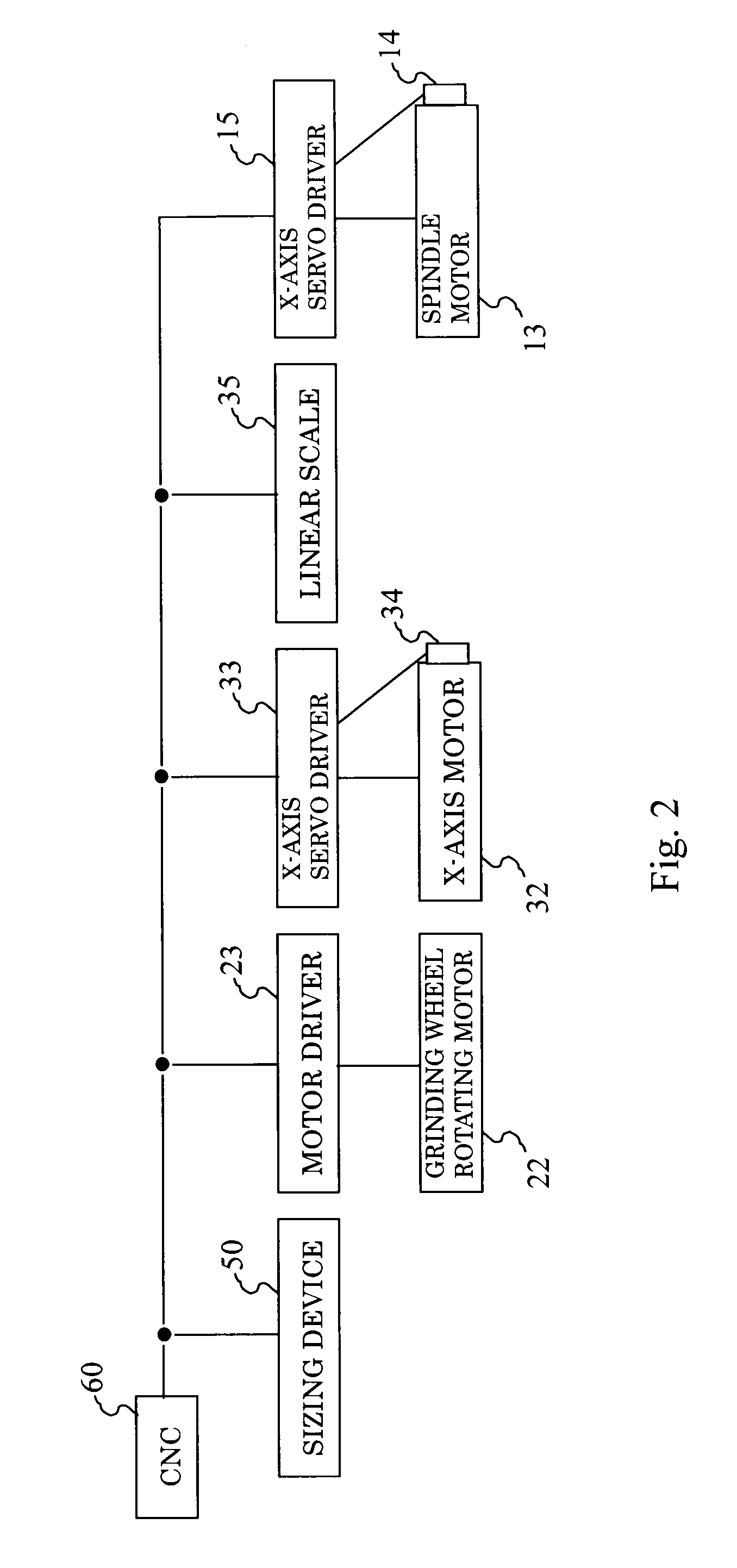
[0030]As shown in FIG. 1, the grinding machine provides a spindle device 10, a grinding wheel supporting device 20, a wheel head driving device 30, a grinding wheel 40, a sizing device 50 and a CNC (Computer Numerical Controller) 60. A workpiece W ground by the grinding machine is a longitudinal cylindrical shaft and the grinding machine performs a grinding to machine a peripheral surface of the workpiece W.

[0031]The spindle device 10 includes a head stock 11, a spindle 12, a spindle motor 13, a spindle encoder 14 and a servo driver 15 for the spindle. The head stock 11 is mounted on an un-illustrated bed. The spindle 12 is supported rotatably around an axis parallel to a Z-axis by penetrating through the spindle head 11. On the spindle 12 is mounted a...

second embodiment

of the Present Invention

[0074]Next the grinding machine of the second embodiment according to the present invention will be explained here in referring to FIG. 7. The grinding machine in the second embodiment is added first gain regulation portion 107 and second gain regulation portion 102 to the X-axis servo driver 33 in the first embodiment. A function of the same number of parts in the second embodiment to that in the first embodiment is same to that in the first embodiment and is eliminated to be explained. Therefore, only differences are explained hereinafter.

[0075]The first gain regulation portion 107 is installed between the first position control portion 106 and the adding circuit 108, and regulates a degree of influence to the first feedback control. Therefore, the first gain regulation portion 107 outputs a value multiplied the commanded velocity value being output from the first position control portion 106 by a value of first gain. The value of the first gain is 0 (zero)...


PUM


Abstract

It is an object of the present invention to provide a machine tool and a machining method thereof which can execute to machine the workpiece more precisely.
The machine tool comprises a tool supporting member 21 relatively movable to a workpiece W along a predetermined axis and supporting a tool 40, a servo motor 32 driving the tool supporting member 21 to the workpiece W along the predetermined axis, a sizing sensor 50 measuring a profile of the workpiece W machined by the tool 40 and outputting a size deviation of measured values from a target profile, and a servo driver 33 driving the servo motor 32 in a feedback control based on the size deviation being output from the sizing sensor 50.

Description

INCORPORATION BY REFERENCE[0001]The present application claims priority under 35 U.S.C. §119 to Japanese Patent Applications No. 2009-018168, filed on Jan. 29, 2009 and No. 2009-018196, filed on Jan. 29, 2009. The contents of these applications are incorporated herein by reference in the entirety.BACKGROUND OF THE INVENTION[0002]1. Field of the Invention[0003]The present invention relates to a machine tool and a machining method thereof, especially the machine tool having a servo motor moving a tool supporting member, and a servo driver driving the servo motor.[0004]2. Description of the Prior Art[0005]It is well known that there are several machine tools controlling a servo motor to move a wheel slide (defined as a “tool supporting member” here) by the servo motor, for example disclosed in a laid-open patent publication of Tokkai 2005-327191. In this disclosed prior machine tool, it is disclosed that a feed back control is executed by detecting a position of the tool supporting mem...

Claims


Application Information

Patent Timeline
IPC IPC(8): G05B19/25G05B1/06
CPCB23Q15/02B24B49/02G05B19/19G05B2219/50074G05B2219/41021G05B2219/45161G05B2219/50062G05B2219/37345
Inventor ABETA, SATOSHIYONEZU, TOSHIHIRO
Owner JTEKT CORP
Why Eureka
Try Eureka