Digitally addressed flat panel x-ray sources

a flat panel x-ray source and digital technology, applied in the direction of x-ray tube target materials, x-ray tube targets and convertors, nuclear engineering, etc., can solve the problems of severe thermal stress in the source, cathode x-ray tube limitations, and damage to the anode, so as to reduce the electromagnetic flux (x-ray) flux, and reduce the x-ray flux available

Inactive Publication Date: 2010-07-29
STELLARRAY
View PDF14 Cites 38 Cited by
  • Summary
  • Abstract
  • Description
  • Claims
  • Application Information

AI Technical Summary

Benefits of technology

[0016]According to one embodiment of the present disclosure an apparatus and method for the X-ray irradiation of materials. This apparatus includes an irradiation chamber, a number of flat electromagnetic (X-ray) sources, a support mechanism, a heat transfer system, and a shielding system. A shielded portal within the shielding system allows access to an interior volume of the irradiation chamber. The shielded portal allows materials to be placed in and withdrawn from the irradiation chamber. When closed, the shielded portal allows a continuous shielded boundary of the interior volume of the irradiation chamber. The electromagnetic sources are positioned on or embedded with interior surfaces of the irradiation chamber. These electromagnetic sources may generate an electromagnetic flux, such as an X-ray flux, where this flux is used to irradiate the interior volume of the irradiation chamber and any materials placed therein. The materials placed within the interior of the chamber may be supported by a low attenuation support mechanism. This low attenuation support mechanism does not substantially reduce the X-ray flux intended to irradiate the materials placed within the interior volume of the irradiation chamber. Additionally the irradiation chamber may have a heat transfer system thermally coupled to the irradiation chamber and electromagnetic sources in order to remove heat from the interior surfaces of the irradiation chamber. The shielding system external to the irradiation chamber prevents unwanted radiation from escaping from within the irradiation chamber.
[0017]Another embodiment of the present disclosure provides a method for the X-ray irradiation of materials. This method involves transporting a work piece or material to be irradiated to an irradiation chamber. The work piece or materials are placed within the irradiation chamber and supported with a mechanism such as a low attenuation support mechanism. This low attenuation support mechanism does not substantially reduce the electromagnetic flux (X-ray) flux within the irradiation chamber. One or more flat electromagnetic (X-ray) sources may be energized to irradiate the interior volume of the irradiation chamber. This allows the work piece or materials to be irradiated within the chamber. Excess heat may be removed with a heat transfer system in order to prevent the irradiation chamber / electromagnetic source from overheating. Additionally the irradiation chamber may be shielded to prevent the irradiation of objects and materials external to the irradiation chamber.
[0018]Yet another embodiment of the present disclosure provides another system for the X-ray irradiation of materials. This system includes an irradiation chamber, a number of flat X-ray sources, a transport mechanism, a low attenuation support mechanism, a heat transfer system, a shielding system, and a process controller. The irradiation chamber has an inner volume wherein the flat X-ray sources are positioned within or on the interior surfaces of the irradiation chamber such that the flat X-ray sources may irradiate the interior volume of the irradiation chamber. The transport mechanism allows materials to travel to and from the irradiation chamber. Within the irradiation chamber the low attenuation support mechanism supports the work pieces or materials to be irradiated while not substantially reducing the X-ray flux available for the irradiation of these objects. The heat transfer system removes heat from the X-ray source and the shielding system external to the irradiation chamber prevents inadvertent irradiation of materials and objects outside the irradiation chamber. The process controller coordinates the operation of the irradiation chamber, X-ray source, heat transfer system and an interlock system which prevents irradiation while access to the interior volume is open.

Problems solved by technology

In a typical X-ray tube operating below 200 kV potential between the cathode and anode, less than 2 percent of the electrical power from the cathode is converted to X-ray flux; the rest is converted to heat, which can damage the anode and cause severe thermal stresses in the source.
While they offer several improvements, these cold cathode X-ray tubes share the limitations of their hot filament tube predecessors in being essentially point sources of X-rays.
It also limits the area of the anode to that of the cathode, making it difficult to produce more than small levels of X-ray flux owing to the difficulty of extracting heat from this small area.
A limitation of this type of X-ray source is that the heat produced in this process can be difficult to manage.
In doing so, thermal stresses will be produced which necessarily limit the power of the X-rays that can be generated in this manner.
X-rays produced by the lower, “reflective” anode will be attenuated first by the cathode arrays and their support structures, and then the thin-film X-ray target, resulting in an inefficient system.
The heat must therefore be transferred through the vacuum enclosure, which will limit the electrical and radiative flux power that can be achieved with this source.
Chemical and gas methods for the remediation of hazards such as anthrax, ricin, or smallpox suffer a number of limitations, including hazards to human operators during their application, lingering hazards after they have been applied, limited effectiveness, long set-up and application times and destruction of electronic and other equipment in the treatment area.
However, point sources of X-rays have limited heat dissipation capacity and therefore will be limited in their ability to cover a large decontamination or sterilization area.
Current point sources of X-rays, however, must place the source at a considerable distance from the imaging object, thereby increasing the bulk of the imaging system, or rely on grazing incidence optical systems to spread and collimate the flux.
These optical systems for point sources of X-rays, however, are bulky, complicated and expensive.
Current tomographic imaging systems using a single or dual X-ray tube source rely on complex and expensive mechanical gantries to move the tube into position for each of a succession of flux emissions.
These, however can not be placed close enough together to enable fine pitch resolution for imaging.
They are also limited in the X-ray flux which can be produced owing to difficulty of dissipating heat from their small anode.
These configurations will also be limited in the pixel pitch which can be obtained.

Method used


Image

  • Digitally addressed flat panel x-ray sources
  • Digitally addressed flat panel x-ray sources
  • Digitally addressed flat panel x-ray sources

Examples


Embodiment Construction

[0033]Preferred embodiments of the present disclosure are illustrated in the FIGs., like numerals being used to refer to like and corresponding parts of the various drawings.

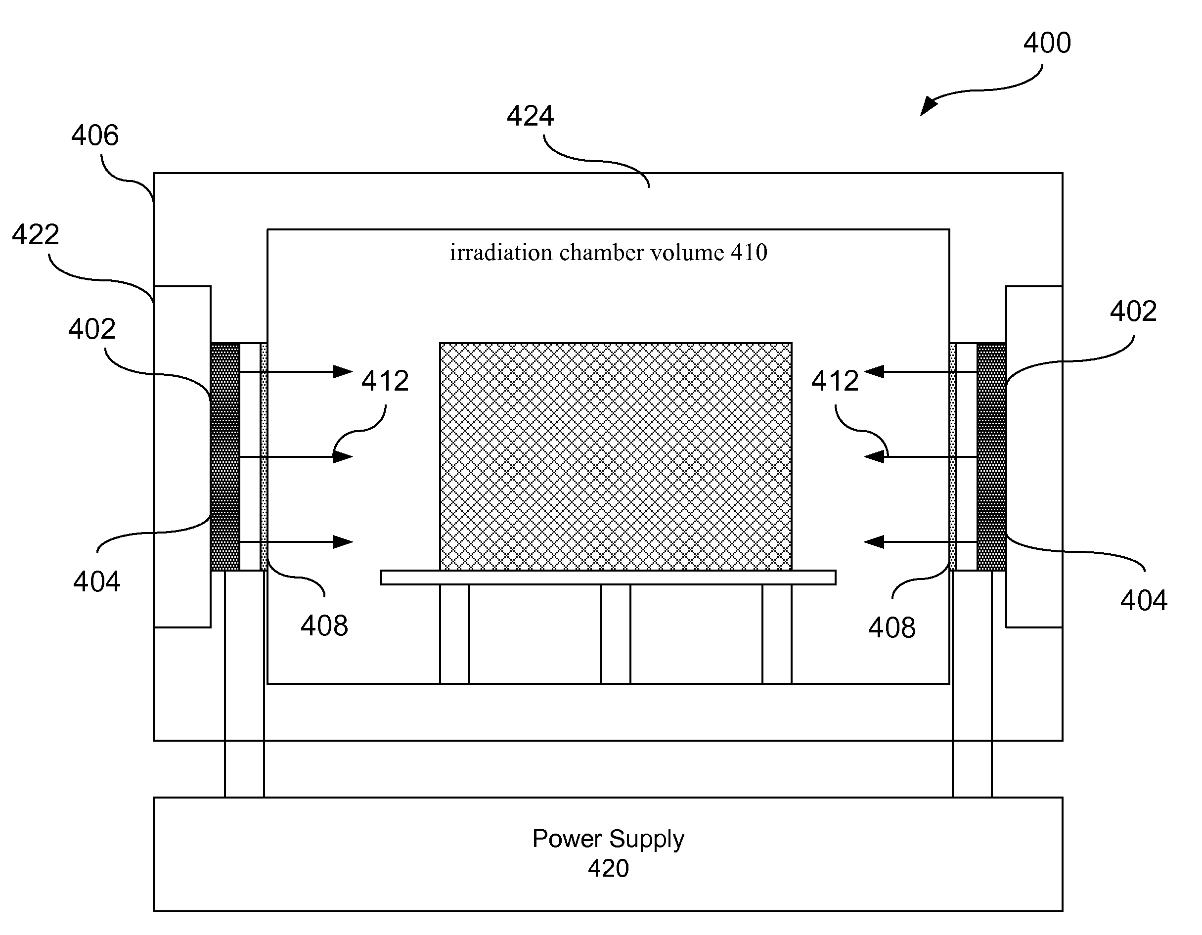
[0034]The present disclosure relates to matrix addressed flat panel x-ray sources for use in applications where location specific addressing of x-ray beams is desired.

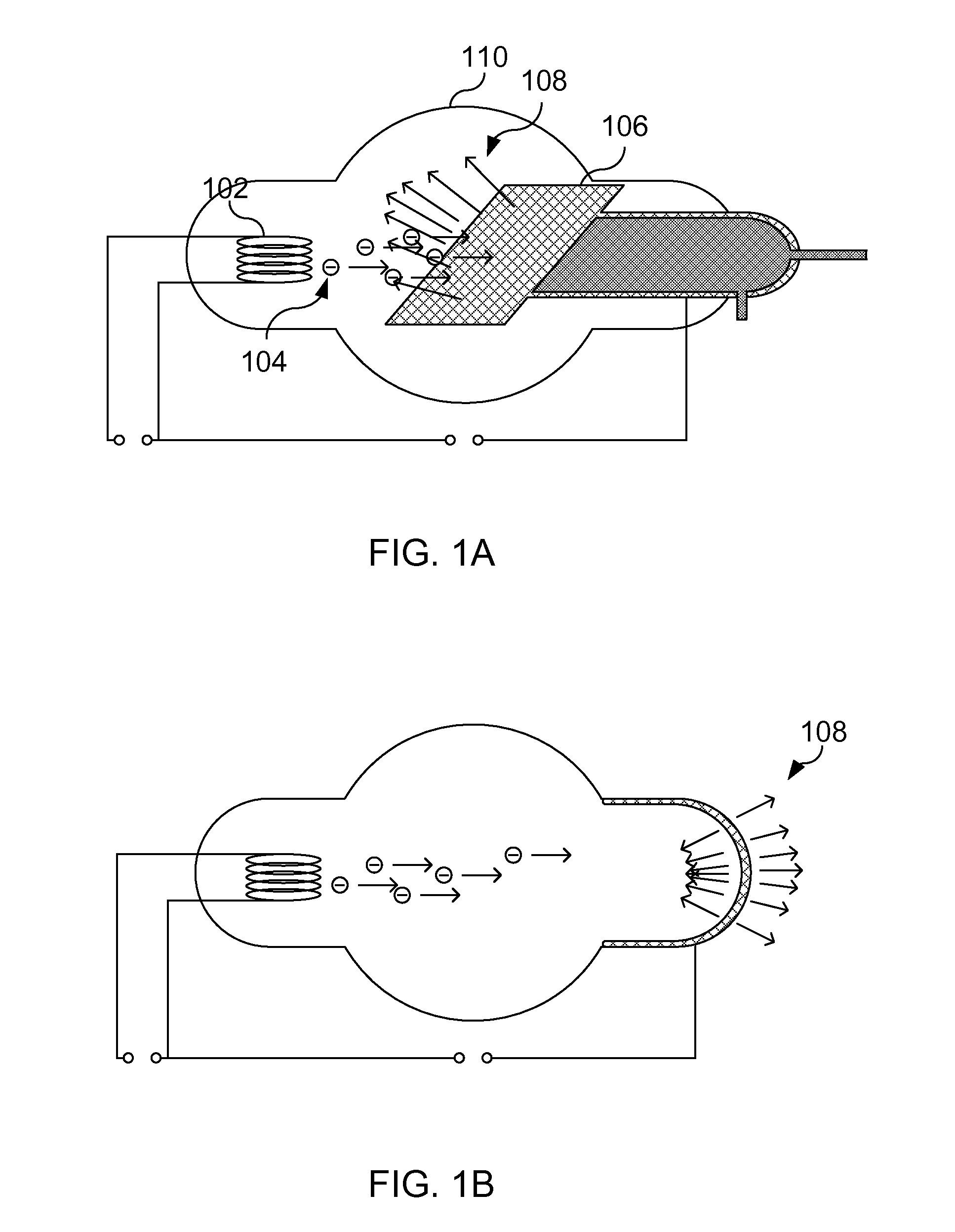
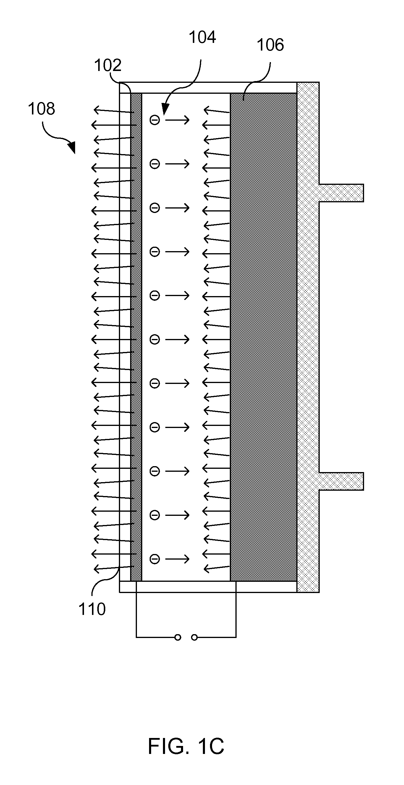
[0035]A conventional x-ray tube includes an anode, grid, and cathode assembly. The cathode assembly generates an electron beam which is directed to a target, by an applied electric field established by the anode. The target in turn emits x-ray radiation in response to the incident electron beam.

[0036]In high current x-ray tubes such as those used in tomographic imaging and radiography, high current and small spot size are desirable while operating at a high anode voltage. For these applications, electron beam current of tens of milliamps to several hundred milliamps is focused onto a small spot to generate a high intensity x-ray beam. To improve co...


PUM


Abstract

An apparatus and method for the X-ray irradiation of materials is provided. This apparatus includes an irradiation chamber, a number of flat electromagnetic (X-ray) sources having a number of addressable cathode emitters, a support mechanism, a heat transfer system, a shielding system, and a process controller. A shielded portal within the shielding system allows access to an interior volume of the irradiation chamber. The electromagnetic sources are positioned on or embedded within interior surfaces of the irradiation chamber. These electromagnetic sources generate an electromagnetic flux, such as an X-ray flux, where this flux is used to irradiate the interior volume of the irradiation chamber and any materials placed therein. The operation of the electromagnetic sources and the number of addressable cathode emitters being controlled by the process controller. The materials placed within the interior of the chamber may be supported by a low attenuation support mechanism. This low attenuation support mechanism does not substantially reduce the X-ray flux intended to irradiate the materials placed within the interior volume of the irradiation chamber.

Description

REFERENCES TO RELATED APPLICATIONS[0001]The present U.S. Utility patent application claims priority pursuant to 35 U.S.C. §120, as a continuation-in-part (CIP), to the following U.S. Utility patent application which is hereby incorporated herein by reference in its entirety and made part of the present U.S. Utility patent application for all purposes:[0002]1. U.S. Utility application Ser. No. 12 / 201,741, entitled “COMPACT RADIATION SOURCE,” (Attorney Docket No. STRY002US1), filed Aug. 29, 2008, pending, which claims priority pursuant to 35 U.S.C. §120 as a continuation to the following U.S. patent application which is hereby incorporated herein by reference in its entirety and made part of the present U.S. Utility patent application for all purposes:[0003]a. U.S. Utility application Ser. No. 11 / 355,692, entitled “COMPACT RADIATION SOURCE,” (Attorney Docket No. STRY002US0), filed Feb. 16, 2006, abandoned.[0004]The present U.S. Utility patent application also claims priority pursuant ...

Claims


Application Information

Patent Timeline
Patent Type & Authority Applications(United States)
IPC IPC(8): G21K5/04H05G1/30H05G2/00
CPCG21K1/025H01J35/065H01J35/08H01J35/14H01J35/16H01J2235/062H05G1/70H01J2235/081H01J2235/086H01J2235/087H01J2235/163H01J2235/18H01J2235/068H01J35/116H01J35/147
Inventor EATON, MARKCHALAMALA, BABUMORE, MITALL
Owner STELLARRAY
Why Eureka
Try Eureka