
Battery cell connection method and apparatus

Inactive Publication Date: 2010-07-29
GM GLOBAL TECH OPERATIONS LLC
View PDF3 Cites 42 Cited by
  • Summary
  • Abstract
  • Description
  • Claims
  • Application Information

AI Technical Summary

Benefits of technology

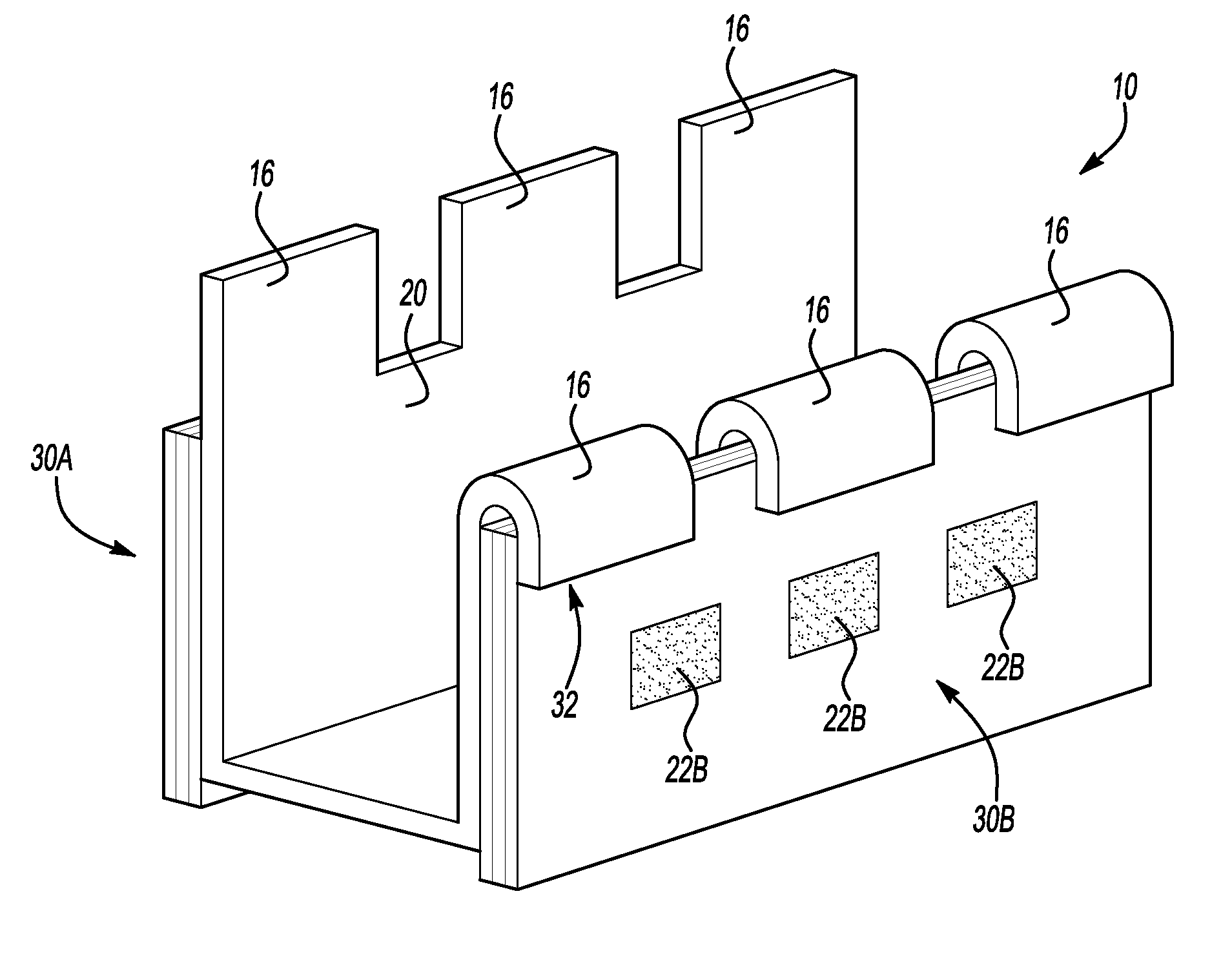
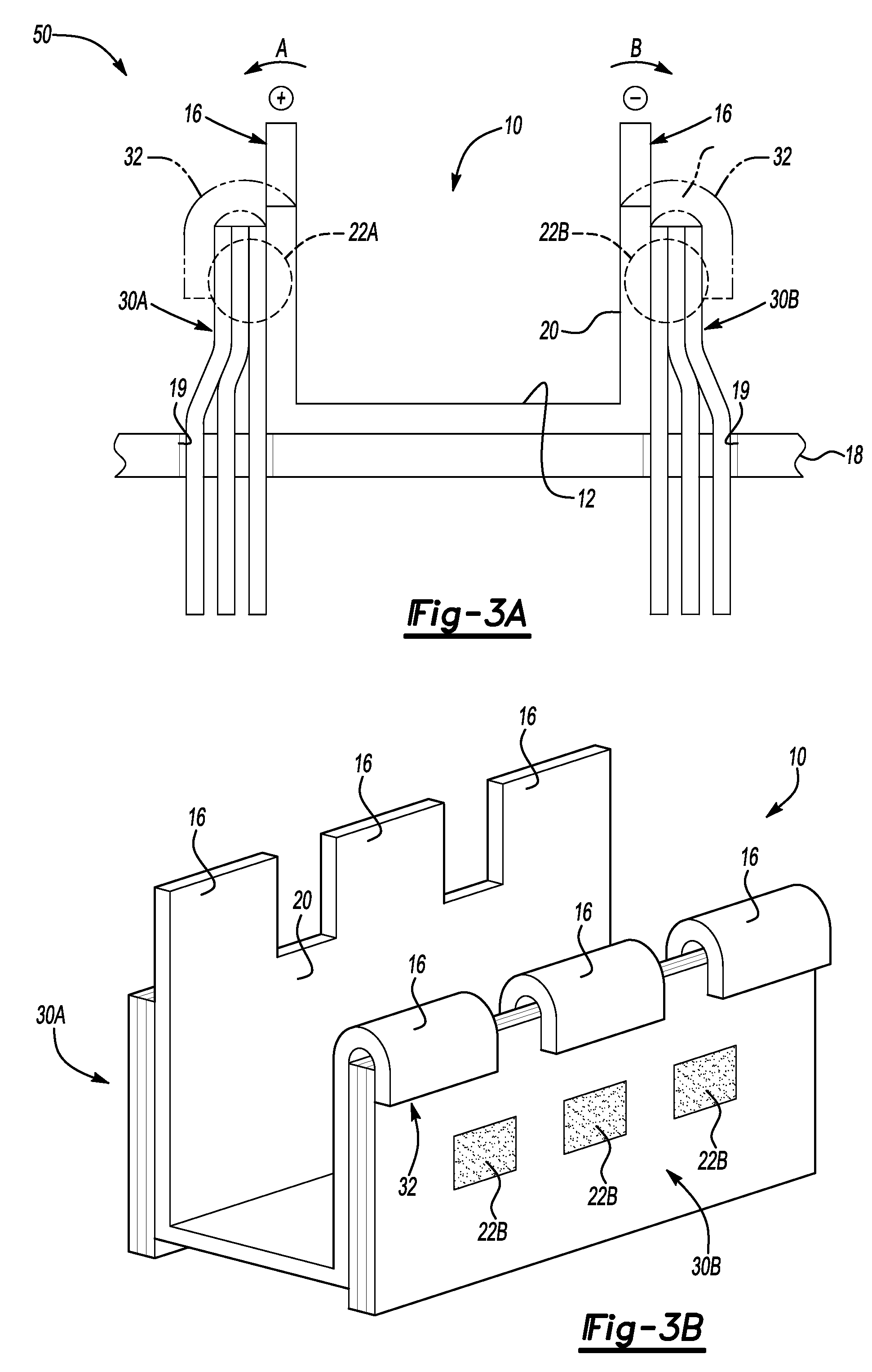
[0009]A method of minimizing shearing stresses in a multi-cell battery module includes fusing, e.g., ultrasonically welding or otherwise joining, a cell tab of each of a plurality of electrochemical cells to a surface of an elongated connecting member to thereby form a welded joint, and then hemming a portion of the connecting member, such as one or more interconnect extensions, around or over the cell tab to thereby form a hem seam. The hem seam can at least partially overlap the welded joint, additionally minimizing the effects of a shearing stress in the welded joint.

Problems solved by technology

When the welded joints are used aboard a hybrid or electric vehicle, the welded joints can degrade over time due to various factors that can occur during common vehicular applications.
For example, a welded joint might be subjected to vibration and / or shearing stresses due to motion of the vehicle.
Likewise, a welded joint can be weakened due to natural electrolytic corrosion, and / or corrosion due to exposure to potentially aggressive chemical vapors and / or aerosols.
Over time, the initial quality of a welded joint can degrade to some extent, a condition that can potentially lead to a reduced level of electrical conductivity at or along the welded joint, with a resultant decrease in output voltage of the battery module.

Method used


Image

  • Battery cell connection method and apparatus
  • Battery cell connection method and apparatus
  • Battery cell connection method and apparatus

Examples


Embodiment Construction

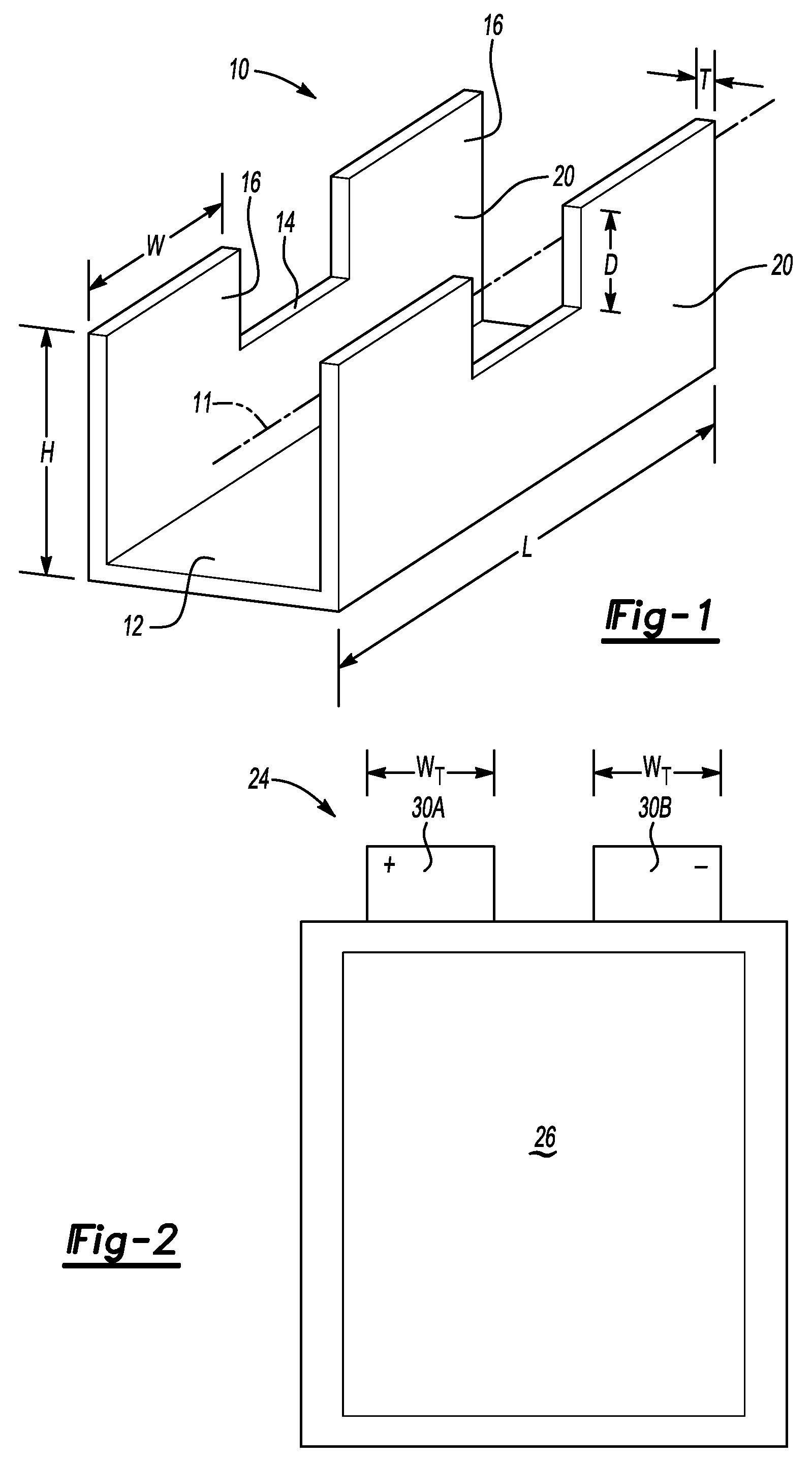
[0017]Referring to the drawings, wherein like reference numbers refer to like components, and beginning with FIG. 1, an elongated interconnecting member 10 is configured for use within a cell stack or battery module 50, as described below with reference to FIG. 3A and 5. By way of example, the battery module 50 could be sufficiently sized to provide the necessary voltage for powering an electric vehicle or a hybrid gasoline / electric vehicle, e.g., approximately 300 to 400 volts or more, depending on the required application. The interconnecting member 10 is constructed of a suitable conductive material, for example pure or elemental copper in one embodiment, or at least approximately 90% copper if an alloy of elemental copper is used, although other conductive embodiments can be envisioned without departing from the intended scope of the invention.

[0018]The interconnecting member 10 is shaped, sized, and / or otherwise configured to form an elongated rail or bus bar. According to one ...


PUM

PropertyMeasurementUnit
Shapeaaaaaaaaaa
Electrical conductoraaaaaaaaaa
Stress optical coefficientaaaaaaaaaa

Abstract

A battery module includes an electrochemical battery cell having a pair of cell tabs and conductive interconnecting members having one or more interconnect extensions. The cell tabs are welded to different interconnecting members to form welded joints, and each interconnect extension is hemmed with respect to the cell tabs to overlap and reinforce the welded joint. The welded joint can be ultrasonically-welded, while the interconnecting member can have a generally U-shaped profile with side walls formed integrally with the interconnect extensions. A method of minimizing effects of a shearing stress in the battery module includes fusing a cell tab or tabs to the interconnecting member to form a welded joint, and then hemming an interconnect extension of the interconnecting member to form a hem seam overlapping the cell tabs. Fusing can include ultrasonically welding the cell tabs to the side walls or other suitable means.

Description

TECHNICAL FIELD[0001]The invention relates to electrochemical cell stack-type battery modules, and in particular to battery cell stacks or modules having welded cell tab connections, and to a method of forming the same.BACKGROUND OF THE INVENTION[0002]Multi-cell electrochemical devices, also referred to as battery cell stacks or multi-cell battery modules, can be used for a variety of different applications, including the powering of various electronic devices, for vehicle propulsion, etc. While conventional battery designs such as alkaline, voltaic pile, and lead-acid batteries have been used in countless household and industrial applications for the past few centuries, evolving battery types such as nickel cadmium (NiCd), nickel-metal hydride (Ni-MH), lithium ion, and lithium ion polymer batteries have displayed particular utility in emerging electric and hybrid gas / electric vehicle propulsion applications, due in large part to their superior energy densities. Such batteries are o...

Claims


Application Information

Patent Timeline
IPC IPC(8): H01M4/02B23K28/00B23K20/10H01M50/503H01M50/516H01M50/522H01M50/534H01M50/536H01M50/54
CPCB23K20/10B23K2201/18H01M2/266B23K2203/12H01M2/202B23K2201/38B23K2101/18B23K2101/38B23K2103/12Y02E60/10H01M50/54H01M50/522H01M50/516H01M50/534H01M50/536H01M50/503
Inventor KHAKHALEV, ALEXANDER D.
Owner GM GLOBAL TECH OPERATIONS LLC
Learn More