
Power supply system and cell assembly control method

a power supply system and cell technology, applied in the field of power supply systems, can solve the problems of inability to say, deformation of the cells configuring the assembled battery, and inability to meet the needs of secondary batteries, and achieve the effect of inhibiting the deformation of secondary batteries and high energy density

Inactive Publication Date: 2010-08-05
PANASONIC CORP
View PDF13 Cites 5 Cited by
  • Summary
  • Abstract
  • Description
  • Claims
  • Application Information

AI Technical Summary

Benefits of technology

[0009]An object of this invention is to provide a safe and secure power supply system that uses a secondary battery with high energy density per unit weight, and which is able to inhibit the deformation of such secondary battery even upon receiving all currents from a generator as a charging current.
[0014]Consequently, the problem of raising the atmospheric temperature of the cell assembly (particularly the first assembled battery 2a as the primary power source) as in cases of using a resistor, which is associated with excessive heat generation, as the lateral flow circuit can be prevented. Thus, it is possible to avoid the problem of the cell deforming due to heat.
[0015]Accordingly, even when using an alkaline storage battery such as a nickel hydride storage battery or a nickel cadmium storage battery or a nonaqueous electrolyte secondary battery such as a lithium ion secondary battery or a lithium polymer secondary battery with high energy density per unit weight as the secondary battery, it is possible to realize a safe and secure power supply system capable of receiving all currents from the generator as a charging current without inducing problems such as the deformation of the secondary battery.
[0016]The present invention is particularly effective when using a cell starter power supply that needs to constantly receiving a charging current from the generator.

Problems solved by technology

Although the lead storage battery has a reaction mechanism that is suitable for charge / discharge with a relatively large current, it cannot be said that the foregoing secondary batteries are suitable for charge / discharge with a large current from the perspective of their reaction mechanism.
With a nonaqueous electrolyte secondary battery such as a lithium ion secondary battery or a lithium polymer secondary battery, while the electrolytic solution containing a nonaqueous electrolyte tend to decompose at the end stage of charging, this tendency becomes prominent when the atmospheric temperature increases, and there is a possibility that the cells configuring the assembled battery will deform due to the rise in the inner pressure of the battery.
Nevertheless, when adopting the first mode, there is a possibility that the constant voltage charger will supply excessive current to the foregoing electrically powered equipment and cause the electrically powered equipment to malfunction.
Moreover, when adopting the second mode, the heat that is generated when the resistor consumes the current will increase the atmospheric temperature of the foregoing secondary battery, and the possibility of the cell deforming cannot be resolved.
Thus, even if a secondary battery with high energy density per unit weight is randomly used to configure the cell assembly, it is difficult to combine it with a constant voltage charger.

Method used


Image

  • Power supply system and cell assembly control method
  • Power supply system and cell assembly control method
  • Power supply system and cell assembly control method

Examples


Embodiment Construction

[0022]The best mode for carrying out the present invention is now explained with reference to the attached drawings.

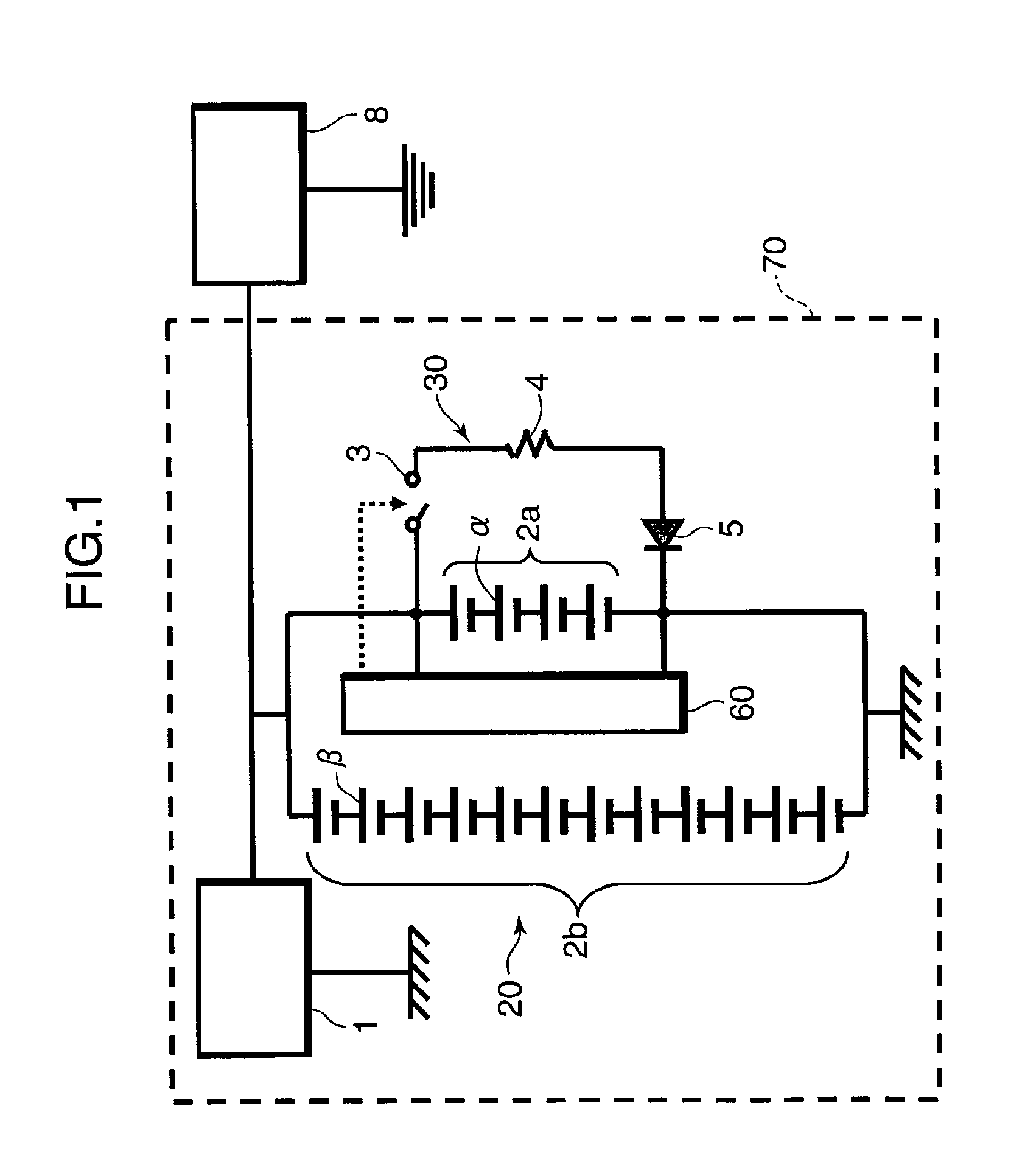
[0023]FIG. 1 is a block diagram explaining the configuration of a power supply system according to an embodiment of the present invention.

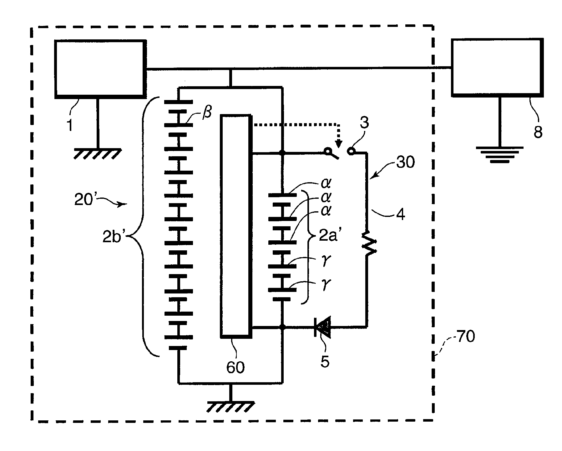
[0024]As shown in FIG. 1, the power supply system 70 comprises a generator 1, a cell assembly 20, a forced discharge unit 30 and a control unit 60. The generator 1 is used for charging the cell assembly 20 and, for instance, is a generator that is mounted on a vehicle and having a constant voltage specification for generating power based on the rotary motion of the engine. The cell assembly 20 includes a first assembled battery 2a in which a plurality (four in the configuration of FIG. 1) of cells α (first cells) are connected in series and a second assembled battery 2b in which a plurality (twelve in the configuration of FIG. 1) of cells β (second cells) are connected in series, and the first assembled battery 2a and the second asse...


PUM


Abstract

The power supply system of this invention includes a cell assembly in which a first assembled battery, formed from a plurality of first cells connected in series, and a second assembled battery, formed from a plurality of second cells connected in series, are connected in parallel, and a generator. An average charging voltage V1 of a first assembled battery is smaller than an average charging voltage V2 of a second assembled battery. The power supply system further has a forced discharge unit capable of forcibly discharging the first assembled battery, and a control unit for measuring a voltage of the first assembled battery, and forcibly discharging the first assembled battery when the foregoing voltage reaches a forced discharge start voltage Va using the forced discharge unit until reaching a forced discharge end voltage Vb.

Description

TECHNICAL FIELD[0001]The present invention relates to a power supply system made up of a cell assembly in which a plurality of cells are combined, and a method of controlling such a cell assembly, and more specifically relates to technology of causing the cell assembly to function as a power source without overcharging the cell as a secondary battery.BACKGROUND ART[0002]An alkaline storage battery such as a nickel hydride storage battery and a nickel cadmium storage battery, and a nonaqueous electrolyte secondary battery such as a lithium ion secondary battery and a lithium polymer secondary battery have higher energy density per unit weight than a lead storage battery, and are attracting attention as a power source to be mounted on mobile objects such as vehicles and portable devices. In particular, if cells made up of a plurality of nonaqueous electrolyte secondary batteries are connected in series to configure a cell assembly with high energy density per unit weight, and mounted ...

Claims


Application Information

Patent Timeline
IPC IPC(8): H02J7/00H01M16/00H02J7/02
CPCB60L11/1868H01M10/44H01M10/482Y02T10/7066Y02T10/7005Y02T10/7011H01M16/00B60L58/20Y02T10/70Y02E60/10H01M10/441H02J7/0013H02J7/0024H01M10/4207H01M4/525H01M10/052H01M10/24H01M10/345H01M10/448H01M10/425
Inventor SUGIYAMA, SHIGEYUKIAOKI, MAMORUSUZUKI, KOHEI
Owner PANASONIC CORP
Learn More