Turbine blade cascade endwall

a turbine blade and cascade technology, applied in the direction of machines/engines, stators, liquid fuel engines, etc., can solve the problems of reducing and achieve the effects of reducing the secondary-flow loss due to the vortex, and improving the performance of the turbine as a whol

Active Publication Date: 2010-08-05
MITSUBISHI POWER LTD
View PDF5 Cites 33 Cited by
  • Summary
  • Abstract
  • Description
  • Claims
  • Application Information

AI Technical Summary

Benefits of technology

[0016]With the turbine according to the fifth aspect of the present invention, because the turbine blade cascade endwall that is capable of suppressing the vortices that occur at the suction surfaces of the turbine stator blades and that is capable of reducing the secondary-flow loss due to the

Problems solved by technology

Therefore, there is a problem in that a pressure gradient (pressure distribution) occurs at the suction surfaces of the turbine stator blades B in the blade height direction (vertical direction in FIG. 15), and, for example, as shown by thin solid lines in FIG. 15, a flow is induced from the tip side (outside in the radial direction: top sid

Method used


Image

  • Turbine blade cascade endwall
  • Turbine blade cascade endwall
  • Turbine blade cascade endwall

Examples


first embodiment

[0033]a turbine blade cascade endwall according to the present invention will be described below, referring to FIGS. 1 to 3.

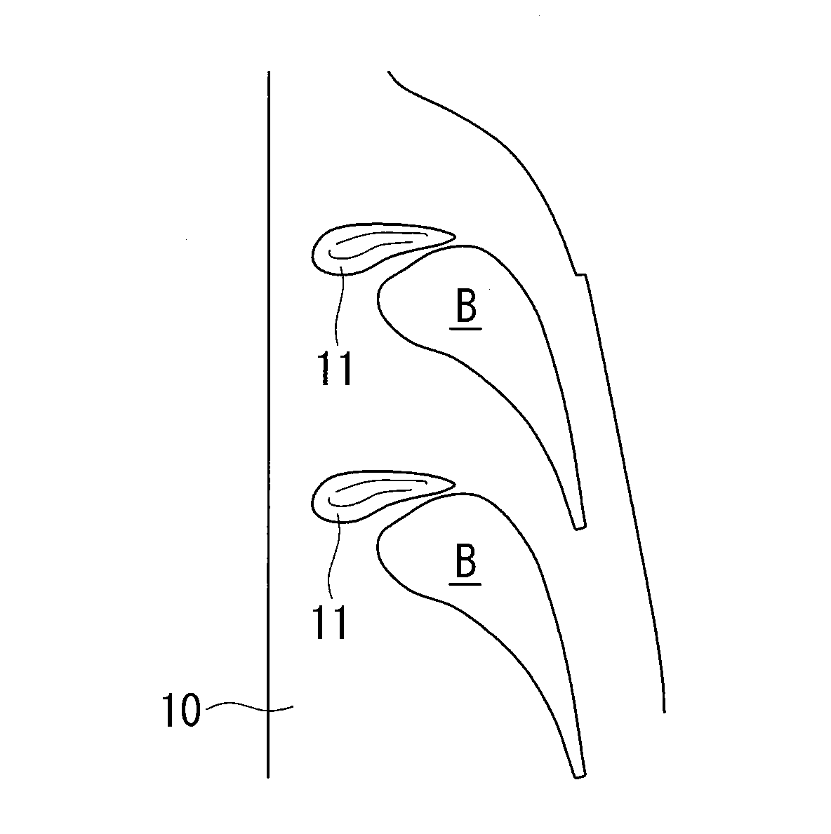
[0034]As shown in FIG. 1, a turbine blade cascade endwall (hereinafter, referred to as “tip endwall”) 10 according to this embodiment has respective convex portions (pressure gradient alleviating parts) 11 between one turbine stator blade B and a turbine stator blade B arranged adjacent to this turbine stator blade B. Note that solid lines drawn on the tip endwall 10 in FIG. 1 indicate contour lines of the convex portions 11.

[0035]The convex portion 11 is a portion that is, as a whole, gently (smoothly) swollen within a range from substantially −30% Cax to +40% Cax and within a range from substantially 0% pitch to substantially 40% pitch.

[0036]Here, 0% Cax indicates a leading edge position of the turbine stator blade B in the axial direction, and 100% Cax indicates a trailing edge position of the turbine stator blade B in the axial direction. In addition − (min...

second embodiment

[0050]a tip endwall according to the present invention will be described based on FIGS. 7 to 9.

[0051]As shown in FIG. 7, a tip endwall 20 according to this embodiment has respective concave portions (pressure gradient alleviating parts) 21 between one turbine stator blade B and a turbine stator blade B arranged adjacent to this turbine stator blade B. Note that solid lines drawn on the tip endwall 20 in FIG. 7 indicate isobathic lines of the concave portions 21.

[0052]The concave portion 21 is a portion that is, as a whole, gently (smoothly) depressed within a range from substantially −50% Cax to +40% Cax and within a range from substantially 0% pitch to substantially 50% pitch.

[0053]Additionally, a bottom point of this concave portion 21 is formed at a position of substantially 30% pitch in a position at substantially 0% Cax. From this position, a first trough extends substantially along (substantially parallel to) the axial direction to a location at substantially −50% Cax; and, fr...

third embodiment

[0058]a tip endwall according to the present invention will be described based on FIGS. 10 to 12. As shown in FIG. 10, a tip endwall 30 according to this embodiment has respective convex portions (pressure gradient alleviating parts) 31 and concave portions (pressure gradient alleviating parts) 32 between one turbine stator blade B and a turbine stator blade B arranged adjacent to this turbine stator blade B. Note that solid lines drawn on the tip endwall 30 in FIG. 10 indicate contour lines of the convex portions 31 and isobathic lines of the concave portions 32.

[0059]The convex portion 31 is a portion that is, as a whole, gently (smoothly) swollen within a range from substantially −30% Cax to +40% Cax and within a range from substantially 0% pitch to substantially 40% pitch (within a range from substantially 0% pitch to substantially 30% pitch in this embodiment).

[0060]A leading-edge-side apex of the convex portion 31 is formed at a position of substantially 20% pitch in a positio...


PUM


Abstract

Provided is a turbine blade cascade endwall that is capable of suppressing a vortex generated on a suction surface of a turbine stator blade and that is capable of reducing secondary-flow loss due to this vortex. A turbine blade cascade endwall that is positioned on a tip side of a plurality of turbine stator blades arranged in a ring form is provided with a pressure gradient alleviating part that alleviates a pressure gradient generated in the blade height direction at a suction surface of the turbine stator blades due to a clearance leakage flow, leaking out of a gap between a tip of a turbine rotor blade located on the upstream side of the turbine stator blades and a tip endwall disposed facing the tip of this turbine rotor blade.

Description

TECHNICAL FIELD[0001]The present invention relates to a turbine blade cascade endwall.BACKGROUND ART[0002]On a turbine blade cascade endwall in a turbine serving as a motive power generator that obtains motive power by converting kinetic energy of a fluid to rotational motion, a so-called “cross flow (secondary flow)” occurs from the pressure side of one turbine blade to the suction side of an adjacent turbine blade.[0003]In order to improve the turbine performance, it is necessary to reduce this cross flow and to reduce secondary-flow loss that occurs due to the cross flow.[0004]Therefore, as a turbine blade cascade endwall that reduces such secondary-flow loss due to a cross flow to improve turbine performance, one having non-axisymmetric irregularities formed thereon has been known (for example, see Patent Document 1).[0005]Patent Document 1: U.S. Pat. No. 6,283,713, Specification.DISCLOSURE OF INVENTION[0006]As shown in FIG. 13, on a turbine blade cascade endwall (tip endwall) 1...

Claims


Application Information

Patent Timeline
IPC IPC(8): F01D9/04
CPCF01D5/143F05D2250/71F01D11/08F01D9/041F01D9/02F01D5/14F01D25/00
Inventor SAKAMOTO, YASUROITO, EISAKUOTOMO, HIROYUKI
Owner MITSUBISHI POWER LTD
Why Eureka
Try Eureka