
Ozonoe sterilizaation process and apparatus

Inactive Publication Date: 2010-08-05
TSO3
View PDF7 Cites 9 Cited by
  • Summary
  • Abstract
  • Description
  • Claims
  • Application Information

AI Technical Summary

Benefits of technology

[0011]It is an object of the invention to provide a reliable and economical method and apparatus for the sterilization of an article with humidified ozone-containing gas, at shortened sterilization cycles.
[0012]It has been surprisingly discovered that significantly shortened sterilization cycle times can be achieved by operating the ozone sterilization with humidified ozone at an elevated temperature of 40 to 60° C. This is contrary to general knowledge which dictates sterilization temperatures as low as possible to avoid premature ozone decomposition. In view of the exponential increase in ozone decomposition with each increase in temperature, one would actually expect longer sterilization cycle times due to decreased ozone concentration at these elevated temperatures.
[0033]means for applying a sufficient vacuum to the sterilization chamber to lower the boiling temperature of water below the treatment temperature.

Problems solved by technology

However, the autoclave destroys heat-sensitive instruments.
However, it has been deemed by national health and safety organizations to be carcinogenic and neurotoxic.
Moreover, ethylene oxide requires long sterilization and aeration periods, since the molecule clings to the surface of instruments.
Although ozone at this humidity can kill most micro-organisms, it may not meet the “worst case scenario” stipulated in North American standards.
The steam is heated to 120° C. Thus, the vapour / ozone mixture used for sterilization presumably has a temperature close to 100° C. However, since the decomposition of ozone increases exponentially with temperature in the range of 20 to 300° C., injecting the water vapour at a temperature of about 120° C. leads to premature ozone decomposition.
Moreover, carrying out the sterilization at an elevated temperature and close to 100° C. will require a substantial cooling down period for the sterilized materials, thereby making the sterilization a lengthy and inefficient process.
Although excellent sterilization results are available with that method, meeting all existing standards, the sterilization cycle is very long.

Method used


Image

  • Ozonoe sterilizaation process and apparatus
  • Ozonoe sterilizaation process and apparatus
  • Ozonoe sterilizaation process and apparatus

Examples


Embodiment Construction

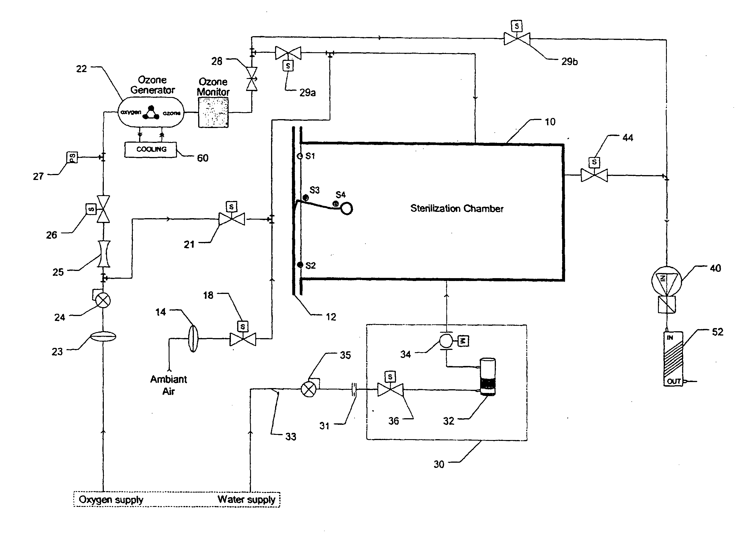
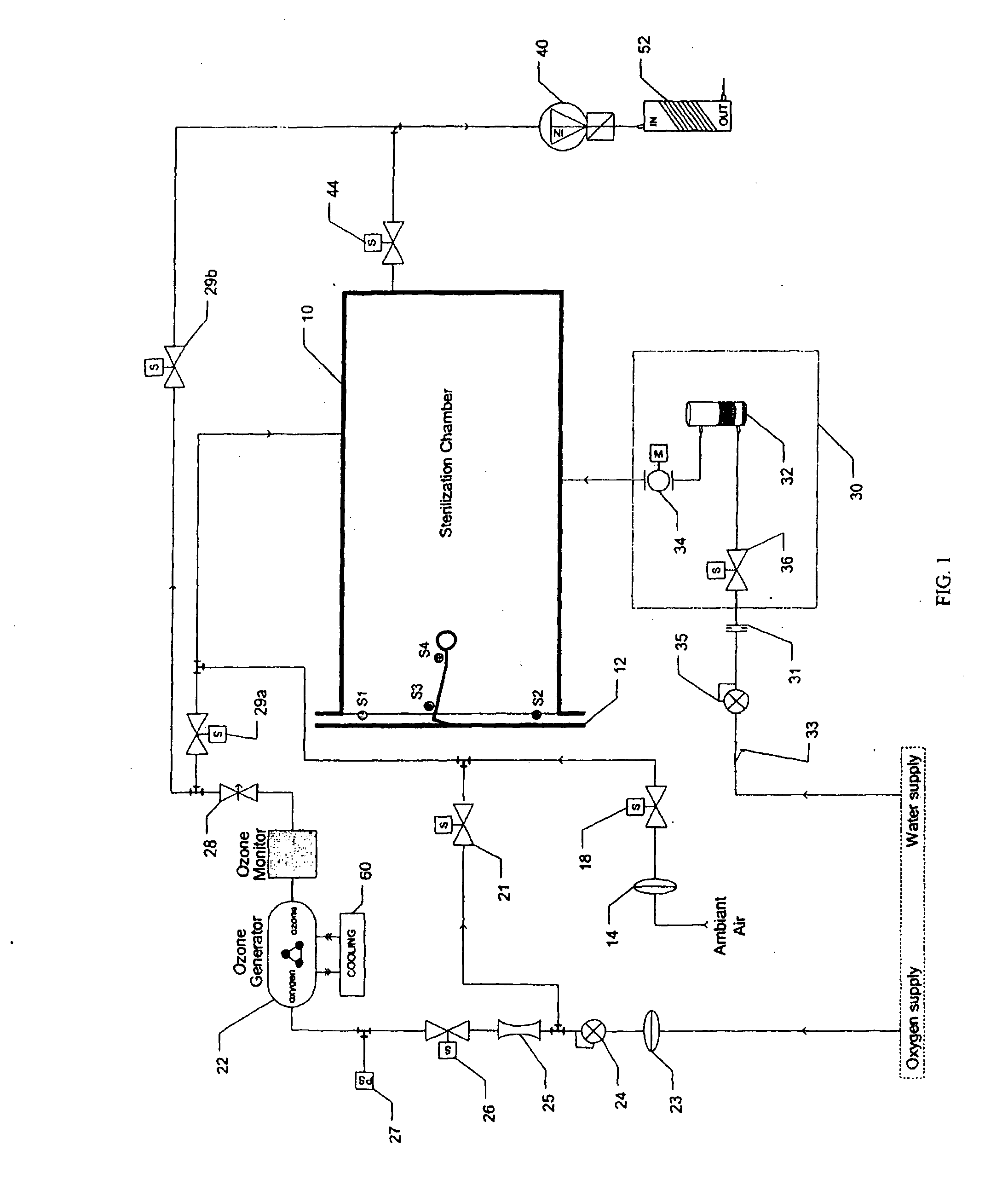
[0041]An ozone sterilizer in accordance with the invention as illustrated schematically in FIG. 1 operates in a relatively simple manner. Medical quality oxygen is subjected in an ozone generator 22 to an electrical field, which converts the oxygen into ozone containing gas. The ozone containing gas is then fed into a humidified sterilization chamber 10 where it sterilizes medical devices. The ozone is subsequently reconverted into oxygen using an ozone catalyst 52. The only residues left at the end of the sterilization cycle are oxygen and clean water vapour.

[0042]Single cycle sterilization with ozone is more efficient and provides for a shorter sterilization cycle than sterilization with EtO and requires few changes in user habits. Moreover, the ozone-based process in accordance with the invention is compatible for use with current packaging, such as sterile pouches and rigid containers. Moreover, the humidified ozone process of the invention provides significantly reduced sterili...


PUM


Abstract

A sterilization method is disclosed, which includes the steps ofproviding a sterilization chamber;placing the article into the sterilization chamber;applying a vacuum of a preselected vacuum pressure to the sterilization chamber;humidifying a sterilization atmosphere in the sterilization chamber;maintaining the sterilization atmosphere at a temperature above 40° C. and at most 60° C.;supplying ozone-containing gas to the sterilization chamber;maintaining the sterilization chamber sealed for a preselected treatment period; andreleasing the vacuum in the sterilization chamber.

Description

FIELD OF THE INVENTION[0001]The present invention relates generally to sterilization equipment and, particularly, to a method and apparatus for ozone sterilization.BACKGROUND OF THE INVENTION[0002]Sterilization is the absolute destruction of any virus, bacteria, fungus or other micro-organism, whether in a vegetative or in a dormant spore state. Conventional sterile processing procedures for medical instruments involve high temperature (such as steam and dry heat units) or toxic chemicals (such as ethylene oxide gas, EtO). Steam pressure sterilization has been the time-honoured method of sterilization. It is fast and cost effective. However, the autoclave destroys heat-sensitive instruments. Thus, since more and more heat-sensitive instruments such as arthroscopes and endoscopes are used in medical treatment, other types of sterilization need to be used.[0003]Ethylene oxide sterilization is used to cold sterilize heat-sensitive instruments. However, it has been deemed by national he...

Claims


Application Information

Patent Timeline
IPC IPC(8): A61L2/20
CPCA61L2/202A61L2/14
Inventor LEGUBE, BERNARD
Owner TSO3
Learn More