Variable magnetic flux drive system

a drive system and variable magnetic technology, applied in the direction of motor/generator/converter stopper, dynamo-electric converter control, electric devices, etc., can solve the problems of poor efficiency and not always achieving optimal performance, and achieve the effect of reducing noise and high efficiency

Active Publication Date: 2010-08-12
KK TOSHIBA
View PDF15 Cites 59 Cited by
  • Summary
  • Abstract
  • Description
  • Claims
  • Application Information

AI Technical Summary

Benefits of technology

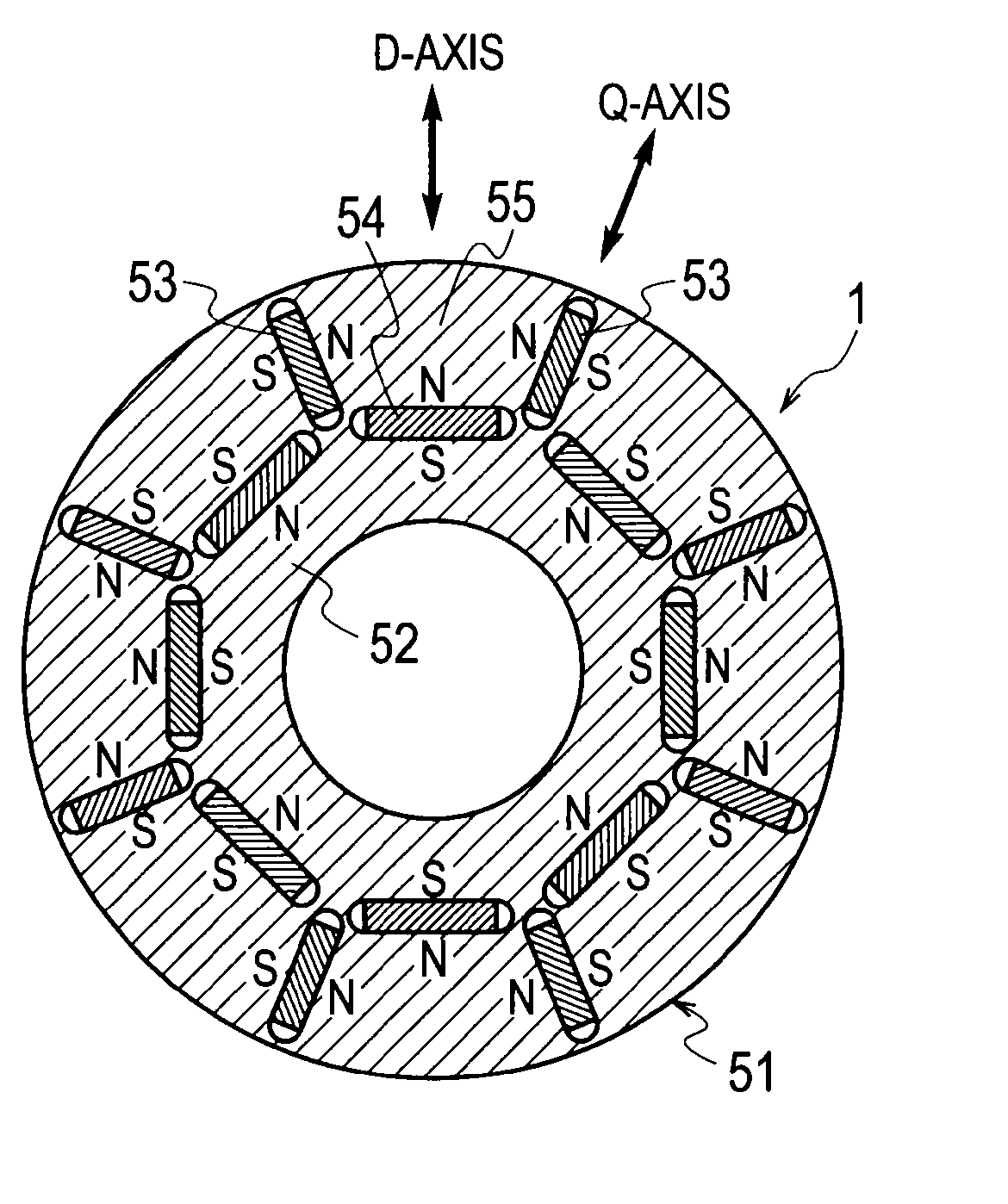
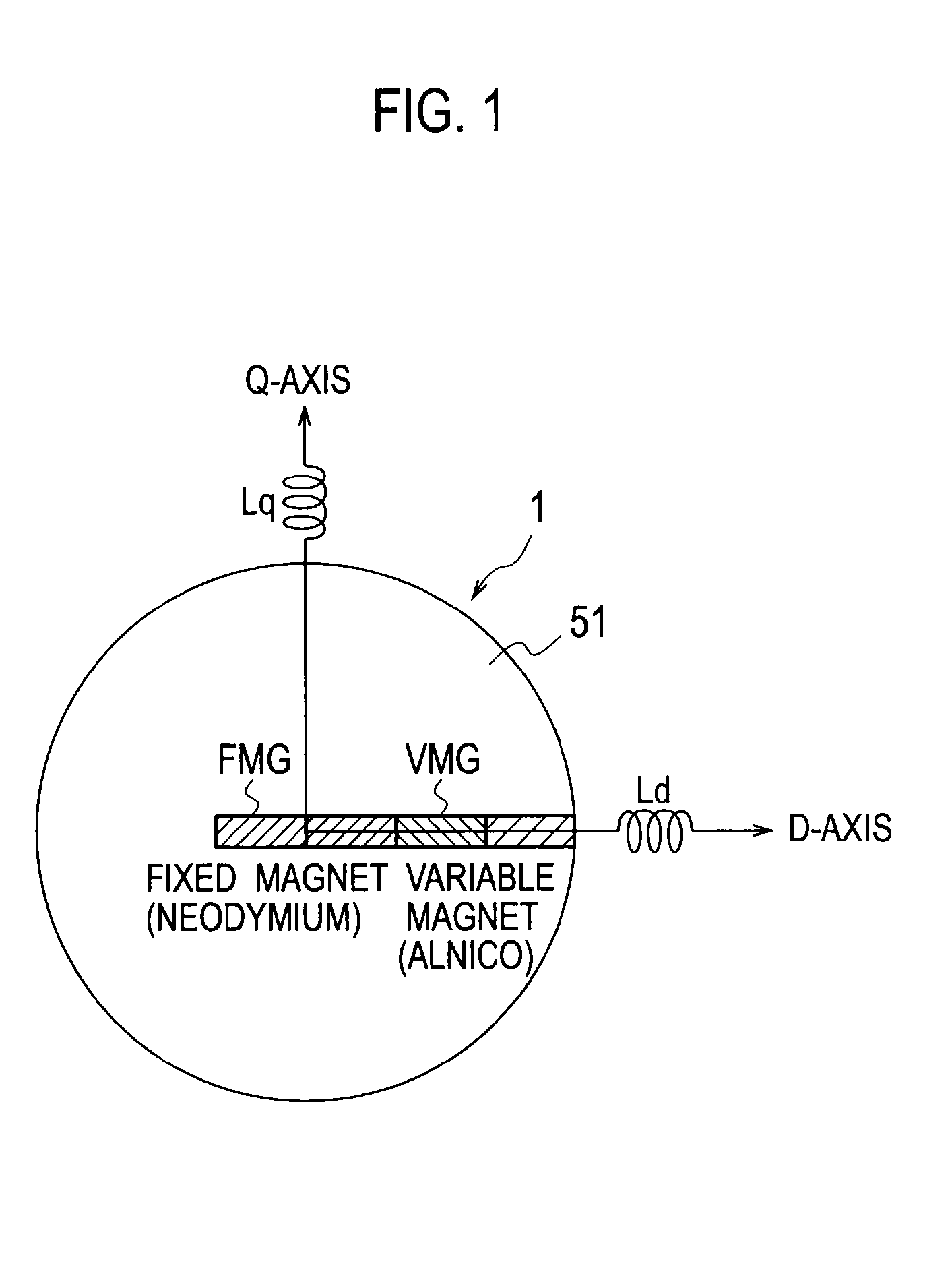
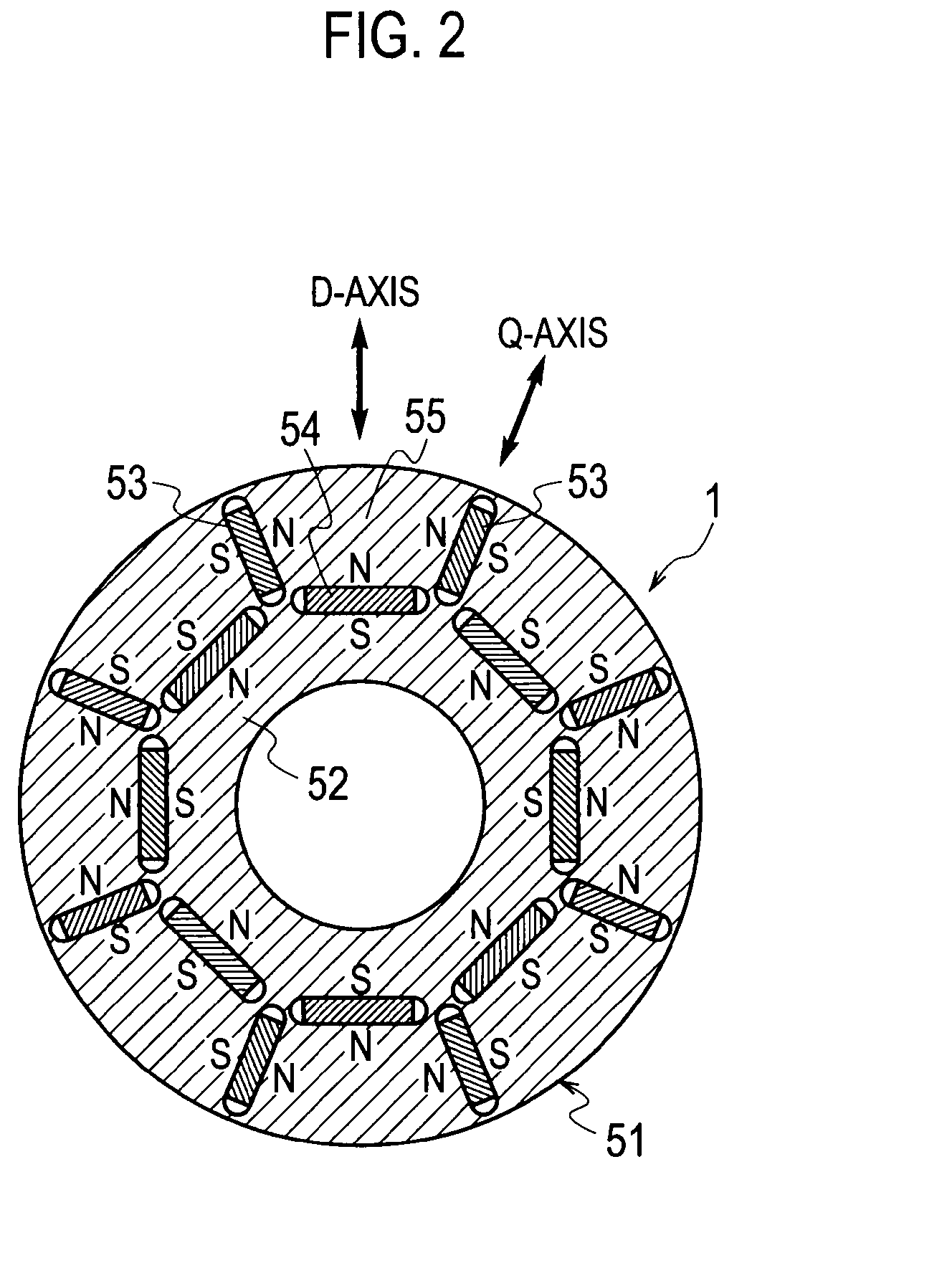
[0015]Therefore, it is possible to utilize a variable magnetic flux drive system using a variable magnetic flux motor that can vary the magnetic flux of the magnet with the current of the inverter. Since this system can vary an amount of magnetic flux of the permanent magnet with a short-time magnetization current according to operational conditions, it can be expected that the efficiency is enhanced as compared with the conventional permanent magnet reluctance motor. Moreover, when the magnet is unnecessary, it is possible to minimize the induced voltage by reducing the amount of magnetic flux.
[0026]With the variable magnetic flux motor drive system, even when it is applied to a device having a plurality of operation modes of different torques and numbers of revolutions, it is possible to select a magnetic flux value most suitable for each operation mode to achieve high efficiency and reduce noise.

Problems solved by technology

Thus, when the permanent magnet reluctance motor is used in a electrical train, an electric car, a hybrid car or the like, it does not always achieve optimum performance in all the operational range in terms of its torque and rotational speed, and some conditions are present on which the efficiency is poor.

Method used


Image

  • Variable magnetic flux drive system
  • Variable magnetic flux drive system
  • Variable magnetic flux drive system

Examples


second embodiment

[0145]A second embodiment will now be described. A variable magnetic flux motor drive system shown in FIG. 11 is configured with the variable magnetic flux motor 1, current detectors 2a and 2b, the DC power supply 3, the inverter 4 that converts a DC power into an AC power, a coordinate converter 5, a PWM circuit 6, a coordinate converter 7, a pseudo differentiator 8, a voltage command computation unit 10, a current reference computation unit 11, the rotational speed command computation unit 12, a rotational speed controller 14, a rotation angle sensor 18, an operation mode management unit 20, the magnetization mode management unit 22, the magnetic flux command computation unit 31 and the magnetization current command computation unit 33.

[0146]The variable magnetic flux motor drive system can be divided into a main circuit and a control circuit. The DC power supply 3, the inverter 4, the variable magnetic flux motor 1, the current detectors 2a and 2b for detecting a motor current an...

third embodiment

[0238]The other configuration is the same as in the third embodiment, and the description thereof will not be repeated.

[0239]The action of this embodiment configured as described above will now be discussed. FIG. 16 is a time chart showing the controlled state of the washing machine to which the variable magnetic flux motor drive system of this embodiment is applied.

[0240]First, in order for the laundry contained in the washing machine to be washed, the operation command Run* is input to the operation mode management unit 20b. Based on the input operation command Run*, the operation mode management unit 20b selects the washing mode from among a plurality of operation modes. The operation mode management unit 20b also outputs the high (H) gate command Gst to the PWM circuit 6 to start the operation of the inverter 4.

[0241]The rotational speed command computation unit 12b computes, based on the washing mode selected by the operation mode management unit 20b, the target rotational spee...

fourth embodiment

[0263]A rotational speed command computation unit 12c computes, based on the operation mode selected by the operation mode management unit 20c, the target rotational speed of the variable magnetic flux motor 1, and outputs the rotational speed command corresponding to the computation result to the rotational speed controller 14, the operation mode management unit 20c and the magnetic flux command computation unit 31c. The other configuration is the same as that of the fourth embodiment, and thus the description thereof will not be repeated.

[0264]The actions of this embodiment configured as described above will now be described. FIG. 18 is a time chart showing the controlled state of the air conditioner to which the variable magnetic flux motor drive system of this embodiment is applied.

[0265]First, the operation command Run* is input to the operation mode management unit 20c so as to adjust the temperature to the set value. The operation mode management unit 20c selects the accelera...


PUM


Abstract

A variable magnetic flux motor drive system includes: a variable magnetic flux motor having a variable magnet which is a low-coercive permanent magnet; an inverter that drives the variable magnetic flux motor 1; an inverter as a magnetization unit which supplies a magnetization current for controlling a magnetic flux of the variable magnet; and a boosting unit boosting an input DC voltage to a predetermined target value to output it to the inverter. The variable magnetic flux motor drive system makes it possible to achieve size reduction and high efficiency, while securing a voltage required for supplying a magnetization current when controlling the magnetic flux of the variable magnet.

Description

TECHNICAL FIELD[0001]The present invention relates to a variable magnetic flux drive system provided with a variable magnetic flux motor having a variable magnet and an inverter for driving the variable magnetic flux motor.BACKGROUND ART[0002]Instead of conventional induction motors (IM motors), permanent magnet synchronous motors (PM motors), which have excellent efficiency and can be expected to be reduced in size and noise, have come to be widely used. For example, as drive motors for railway cars and electric cars, the PM motors have come to be utilized.[0003]Since an IM motor generates a magnetic flux itself by an excitation current from a stator, it has a technical problem of causing a loss due to flowing of the excitation current.[0004]On the other hand, since a PM motor a motor including a permanent magnet in its rotor to output a torque by utilizing its magnetic flux, it is free from such a problem in an IM motor. However, a PM motor generates an induced voltage (counter-el...

Claims


Application Information

Patent Timeline
Patent Type & Authority Applications(United States)
IPC IPC(8): H02P27/00
CPCB60L15/025Y02T10/7275H02K1/2766H02K21/046H02P21/0089H02P21/12H02P25/08Y02T10/641Y02T10/643B60L1/003B60L3/003B60L9/28B60L11/1803B60L15/007B60L15/20B60L2220/14B60L2240/12B60L2240/34B60L2240/36B60L2240/421B60L2240/423B60L2240/547B60L2240/549B60L2240/527Y02T10/7005B60L2200/26B60L50/51H02P25/024Y02T10/64Y02T10/70Y02T10/72
Inventor YUUKI, KAZUAKISAKAI, KAZUTOMOCHIKAWA, HIROSHI
Owner KK TOSHIBA
Why Eureka
Try Eureka