Method to strip a portion of an insulated wire

a technology of insulated wire and stripping method, which is applied in the direction of laser beam welding apparatus, radiating element structure form, manufacturing tools, etc., can solve the problems of reduced space available, large number of connections, and extremely small diameter of wires used

Inactive Publication Date: 2010-08-12
HID GLOBAL GMBH
View PDF4 Cites 84 Cited by
  • Summary
  • Abstract
  • Description
  • Claims
  • Application Information

AI Technical Summary

Benefits of technology

[0012]It is therefore an aim of the present invention to propose a method to strip a

Problems solved by technology

In the manufacturing of small electronic components, a difficulty resides in the extremely small diameter of the wires used, in the high numbers of connections to be made in a very short time and in the very reduced space available.
Additionally, security (for the handling of laser, flames or gases) or quality (strict handling of the stripped insulation particles in order to keep clean rooms) requirements make that available solutions are not always scalable (in terms of yield, costs and ease to use) for high production volume.
Stripping solutions as proposed in U.S. Pat. No. 4,693,778 or U.S. Pat. No. 4,031,612 for example and which are integrated in the manufacturing device, are not working at full satisfaction.
Finally, the used wire stripping techniques have not be proven to be effective enough for high production volume and for the most currently used bonding technique, that is the direct thermo-compression of an insulated portion of wire as described in U.S. Pat. No. 6,233,818.
The insulated portion of the wire is pressed directly against the contact pad of the chip or the chip module by a thermode w

Method used


Image

  • Method to strip a portion of an insulated wire
  • Method to strip a portion of an insulated wire
  • Method to strip a portion of an insulated wire

Examples


Embodiment Construction

[0030]The invention will be better understood by the following detailed description taken together with the following drawings:

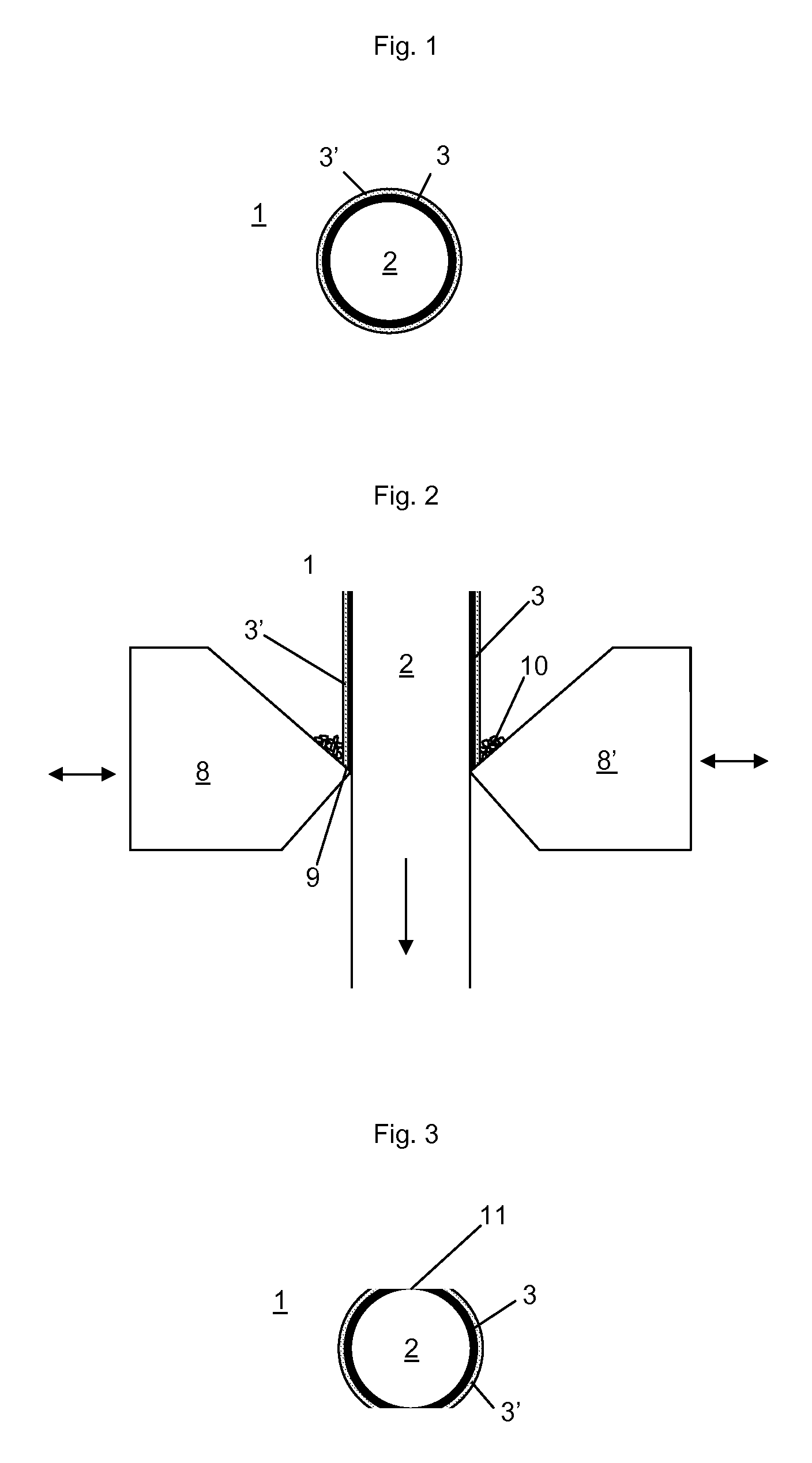
[0031]FIG. 1 shows a cross section of an insulated wire

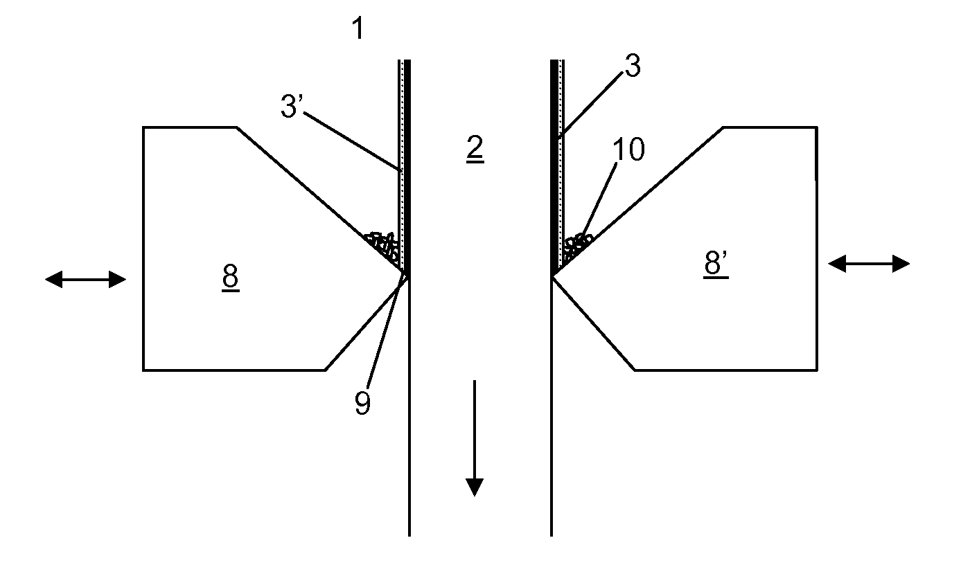
[0032]FIG. 2 shows a wire being stripped by a mechanical stripper

[0033]FIG. 3 shows a cross section of a wire stripped without preliminary flattening

[0034]FIG. 4 shows a cross section a wire after a flattening step of the method of the invention

[0035]FIG. 5 shows a cross section of a wire after the stripping method of the invention

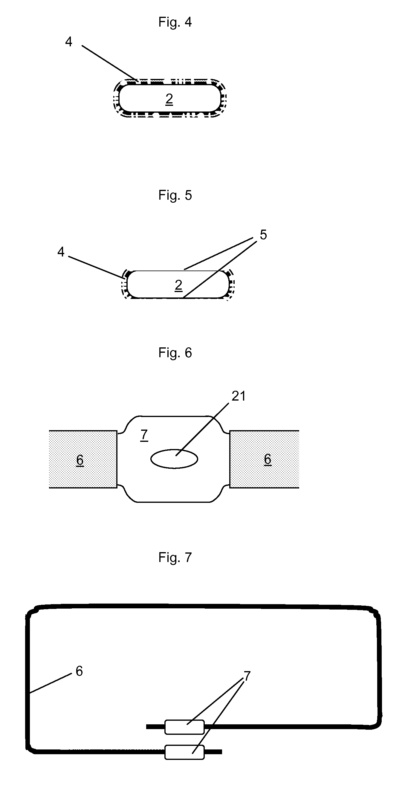
[0036]FIG. 6 shows a top view of a stripped portion of a wire according the invention

[0037]FIG. 7 shows a top view of a wire with two stripped portions according the invention

[0038]FIG. 8 shows a wire stripping machine according the invention

[0039]FIG. 9 shows a top view of a crossover bridge

[0040]FIG. 10 shows a top view of an antenna circuit according the invention

[0041]FIG. 11 shows a wire being stripped by laser radiation according the invention

[0042]FIG. 1 shows an insulat...


PUM

PropertyMeasurementUnit
Fractionaaaaaaaaaa
Diameteraaaaaaaaaa
Diameteraaaaaaaaaa

Abstract

According to the method of stripping a portion of a wire of the invention, the insulated wire including the wire core are first flattened before the insulation is stripped away. The flattening eases the stripping as the insulation is partially cracked and dissociated of the wire core, and the stripping is more efficiently applied on a flat surface. A wire stripping machine and a transponder antenna with stripped portions are also claim as being part of the invention.

Description

FIELD OF THE INVENTION[0001]The present invention relates to a method to strip a portion of an insulated wire and a machine carrying out this method. This method is advantageously used for the manufacturing of electronic components like transponders, whose antenna is commonly made of very thin insulated wires, more particularly in the case of embedded wire antennas for HF transponders.STATE OF THE ART[0002]Wire stripping per se is as old as the use of insulated wire. Electric and electronic engines and devices are commonly using insulated wires the ends of which have to be stripped in order to realize an appropriate electrical connection. In case of electrical installations, this is commonly achieved by hand tools comprising a pair of stripping jaws manually activated. In case of industrial production, automatic machines have been developed to cut, strip and handle continuous insulated wires on a very high frequency base.[0003]In the last decades, numerous machine to strip a portion...

Claims


Application Information

Patent Timeline
IPC IPC(8): H01Q11/12B23K26/38
CPCH02G1/1285H02G1/1256H01Q1/38H02G1/1248Y10T29/4517Y10T29/49989
Inventor MICHALK, MANFRED
Owner HID GLOBAL GMBH
Why Eureka
Try Eureka