Method And Apparatus for Load-Locked Printing

a technology of patterned film and load-locked printing, which is applied in the direction of printing, coating, inking apparatus, etc., can solve the problems of inefficiency of process, difficult use of shadow masks over large areas, and increasing coating of shadow masks, so as to prevent oxidation or contamination

Active Publication Date: 2010-08-12
KATEEVA
View PDF98 Cites 178 Cited by
  • Summary
  • Abstract
  • Description
  • Claims
  • Application Information

AI Technical Summary

Benefits of technology

[0012]The disclosure relates to a method and apparatus for preventing oxidation or contamination during a thermal jet printing operation. The thermal jet printing operation may include OLED printing and the printing material may include suitable ink composition. In an exemplary embodiment, the printing process is conducted at a load-locked printer housing having one or more chambers. Each chamber is partitioned from the other chambers by physical gates or fluidic curtains. A controller coordinates transportation of a substrate through the system and purges the system by timely opening appropriate gates. The substrate may be transported using gas bearings which are formed using a plurality of vacuum and gas input portals. The controller may also provide a non-oxidizing environment within the chamber using a gas similar to, or different from, the gas used for the gas bearings. The controller may also control the printing operation by energizing the print-head at a time when the substrate is positioned substantially thereunder.

Problems solved by technology

This process is inefficient as the entire substrate must be coated, even though only the regions exposed through the shadow mask require a film.
Furthermore, the shadow mask becomes increasingly coated with each use, and must eventually be discarded or cleaned.
Finally, the use of shadow masks over large areas is made difficult by the need to use very thin masks (to achieve small feature sizes) that make said masks structurally unstable.
Furthermore, ink jet printing is conventionally limited to the use of single layer OLED film stacks, which typically have lower performance as compared to multilayer stacks.
The single-layer limitation arises because printing typically causes destructive dissolution of any underlying organic layers.
Finally, unless the substrate is first prepared to define the regions into which the ink is to be deposited, a step that increases the cost and complexity of the process, ink jet printing is limited to circular deposited areas with poor thickness uniformity as compared to vapor deposited films.
The material quality is also lower due to structural changes in the material that occur during the drying process and due to material impurities present in the ink.
No conventional technique combines the large area patterning capabilities of ink jet printing with the high uniformity, purity, and thickness control achieved with vapor deposition for organic thin films.
Because ink jet processed single layer OLED devices continue to have inadequate quality for widespread commercialization, and thermal evaporation remains impractical for scaling to large areas, it is a major technological challenge for the OLED industry to develop a technique that can offer both high film quality and cost-effective large area scalability.
Each of these approaches is inefficient as compared to the direct deposition of the desired pattern, either because it wastes material or requires additional processing steps.

Method used


Image

  • Method And Apparatus for Load-Locked Printing
  • Method And Apparatus for Load-Locked Printing
  • Method And Apparatus for Load-Locked Printing

Examples


Embodiment Construction

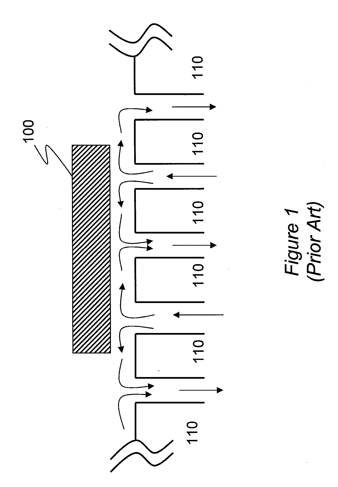
[0027]FIG. 1 is a schematic representation of a conventional substrate floatation system. More specifically, FIG. 1 shows a portion of a flotation system in which substrate 100 is supported by air bearings. The air bearings are shown schematically as arrows entering and leaving between baffles 110. The substrate floatation system of FIG. 1 is typically housed in a sealed chamber (not shown). The chamber includes multiple vacuum outlet ports and gas bearing inlet ports, which are typically arranged on a flat surface. Substrate 100 is lifted and kept off a hard surface by the pressure of a gas such as nitrogen. The flow out of the bearing volume is accomplished by means of multiple vacuum outlet ports. The floating height is typically a function of the gas pressure and flow. In principle, any gas can be utilized for such a substrate floatation system; however, in practice it is preferable to utilize a floatation gas that is inert to the materials that come into contact with the gas. A...


PUM

PropertyMeasurementUnit
thicknessaaaaaaaaaa
thicknessaaaaaaaaaa
purityaaaaaaaaaa

Abstract

The disclosure relates to a method and apparatus for preventing oxidation or contamination during a circuit printing operation. The circuit printing operation can be directed to OLED-type printing. In an exemplary embodiment, the printing process is conducted at a load-locked printer housing having one or more of chambers. Each chamber is partitioned from the other chambers by physical gates or fluidic curtains. A controller coordinates transportation of a substrate through the system and purges the system by timely opening appropriate gates. The controller may also control the printing operation by energizing the print-head at a time when the substrate is positioned substantially thereunder.

Description

[0001]The application claims the filing-date priority of Provisional Application No. 61 / 142,575, filed Jan. 5, 2009, the disclosure of which is incorporated herein in its entirety; the application also claims priority to U.S. patent application Ser. No. 12 / 139,391 filed Jun. 13, 2008, the disclosure of which is incorporated herein in its entirety.BACKGROUND[0002]1. Field of the Invention[0003]The disclosure relates to a method and apparatus for efficient deposition of a patterned film on a substrate. More specifically, the disclosure relates to a method and apparatus for supporting and transporting a substrate on gas bearing during thermal jet printing of material on a substrate.[0004]2. Description of Related Art[0005]The manufacture of organic light emitting devices (OLEDs) requires depositing one or more organic films on a substrate and coupling the top and bottom of the film stack to electrodes. The film thickness is a prime consideration. The total layer stack thickness is abou...

Claims


Application Information

Patent Timeline
Patent Type & Authority Applications(United States)
IPC IPC(8): B41J2/05
CPCB05B17/0638B41J2/14B41J11/0015B41J29/393B41J2202/09B41J2202/16B41J2/015H01L51/0005H01L51/56B05C13/02H05B33/10H01L33/005B41M5/0011H01L21/67784B05D5/00H10K71/135H10K71/00B05C15/00H01L21/67201B41M5/0047B05B17/0646B05C5/0208B41J2/16505C23C4/137B41J2/315
Inventor SOMEKH, SASSVRONSKY, ELIYAHU
Owner KATEEVA
Why Eureka
Try Eureka